Variations in the manufacturing process using a CAD design can result in slight changes in size and dimensions from the original design. In order to communicate the acceptable tolerances in these potential variations, manufacturers and mechanical engineers make use of GD&T, sometimes written as GD and T, which stands for Geometric Dimensioning and Tolerancing.
Let’s break down exactly what this incredibly important symbol language is, the symbols and components’ meaning.
What is GD&T? Origin and Why Do MEs Use It?
Prior to the use of GD&T, an X-Y area was used to specify manufacturing features. However, using X-Y areas could lead to the production of a false negatives on inspection.
The position of the feature would be defined in relation to the intended position, if accurate tolerancing specifications were used.
A feature could still be within a circular tolerance, but not within the X-Y square.
During World War II, naval weapons engineer Stanley Parker discovered this issue while attempting to measure torpedoes.
Between 1940 and 1950, Parker created a new system that removed the issue of false negatives, creating GD&T to be a more cost- and time-efficient system.
There are currently two standards for GD&T, one defined by the American Society of Mechanical Engineers and known as the ASME standard and the other applying to the rest of the world and known as the ISO standard.
As per the ISO standard, GD&T is broken down into three sections:
- Geometrical product specifications – refer to the basic geometry of an object, such as size, shape, and positional relationship.
- Tolerance – refers to the degrees of error that are allowable within specific designs.
- Geometric tolerance – combines the two above concepts and indicates the allowable errors in position, size, and form.
Is there a difference between ASME and ISO?
Yes. While there is an increasing movement to unify the two systems, there are two key areas in which they differ:
- Some of the shared symbols between ASME and ISO do not have the same meanings.
- The details of control can differ between ASME and ISO even when the indications are the same. This is because of differences in indications and concepts.
GD&T Tolerancing Guidelines
Before we get into the nuts and bolts of GD&T, there are some general guidelines that apply to all GD&T tolerancing:
- Accuracy, completeness, and clarity are vital to any engineering drawing. These are used to convey the design without adding additional complexity or unnecessary restrictions.
There are several steps you can take to improve the clarity of any design, including:
- Draw dimensions and tolerances outside of the part’s boundaries and apply them to visible lines using true profiles.
- Make sure you always use a unidirectional reading direction.
- Make the best use of white space.
- Stagger your dimensions.
- Always make sure you are conveying the function of the part.
- Design for the loosest tolerances in order to keep manufacturing costs low.
- Add a general tolerance for all dimensions at the bottom of your design and add specific tolerances where needed.
- Always provide tolerances for functional features and their interrelations first before moving on to the rest of the design.
- If at all possible, leave the GD&T tolerancing to the manufacturer.
- There is no need to specify a 90-degree angle. It is universally assumed.
- The industry standard is that all dimensions and tolerances remain valid at 20 °C / 101.3 kPa unless indicated otherwise.
GD&T Symbols and Their Meaning
As we mentioned earlier, GD&T is a symbolic engineering language. As part of our guide, we’ll be breaking down what those GD and T symbols mean.
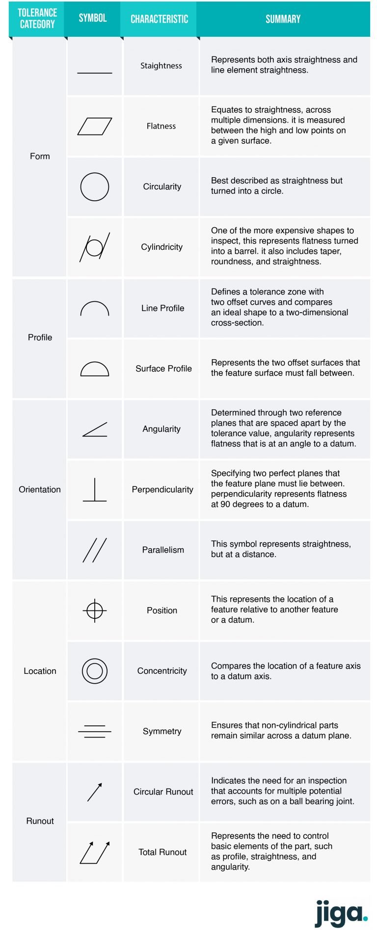
GD&T is a featured-based symbology, with different controls specifying each feature. The symbols used to designate the tolerance of each feature fall into five primary categories:

Yoav A

Head of Design
Form controls
Form controls specify the shape of a given feature, and the symbols used indicate:
- Straightness – This represents both axis straightness and line element straightness.
- Flatness – This equates to straightness, across multiple dimensions. It is measured between the high and low points on a given surface.
- Circularity – This is best described as straightness but turned into a circle.
- Cylindricity – One of the more expensive shapes to inspect, this represents flatness turned into a barrel. It also includes taper, roundness, and straightness.
Profile controls
Profile controls are used to indicate the three-dimensional tolerance zone around any given surface and the symbols used indicate:
- Line Profile – defines a tolerance zone with two offset curves and compares an ideal shape to a two-dimensional cross-section.
- Surface Profile – represents the two offset surfaces that the feature surface must fall between.
Orientation controls
Orientation controls govern any dimensions which vary at angles, and the symbols represent:
- Angularity – Determined through two reference planes that are spaced apart by the tolerance value, angularity represents flatness that is at an angle to a datum.
- Perpendicularity – Specifying two perfect planes that the feature plane must lie between. Perpendicularity represents flatness at 90 degrees to a datum.
- Parallelism – This symbol represents straightness, but at a distance.
Location controls
As you might expect, location controls define the location of a feature by using linear dimensions. The symbols represent:
- Position – This represents the location of a feature relative to another feature or a datum.
- Concentricity – Compares the location of a feature axis to a datum axis.
- Symmetry – ensures that non-cylindrical parts remain similar across a datum plane.
Runout controls
The runout controls are there to specify the amount that a particular feature can vary in relation to the datum points. The symbols represent:
- Circular Runout – indicates the need for an inspection that accounts for multiple potential errors, such as on a ball-bearing joint.
- Total Runout – represents the need to control basic elements of the part, such as profile, straightness, and angularity.
Datums and Features
At the bottom of the image above you can see two additional symbols representing the datum and the feature control frame.
The datum refers to the Datum Reference Frame (DRF). In design engineering, the DRF represents a cartesian coordinate system in three dimensions.
This is hugely important as it essentially represents the framework of the geometric system that provides the G in GD&T.
The DRF is used to establish the required three translational and three rotational degrees of freedom to create the DOF or Six Degrees of Freedom.
As part of the manufacturing process, the DOF needs to be constrained, so part designs are mated to the DRF.
What Is the Difference Between Datums and Datum Features?
When it comes to GD&T, datums are defined as a combination of components, such as points, planes, and lines, that constitute the DRF. These components are considered both theoretical and perfect.
Datum Features, on the other hand, refers to the physical features of the part in question. These features are considered physical and therefore imperfect.
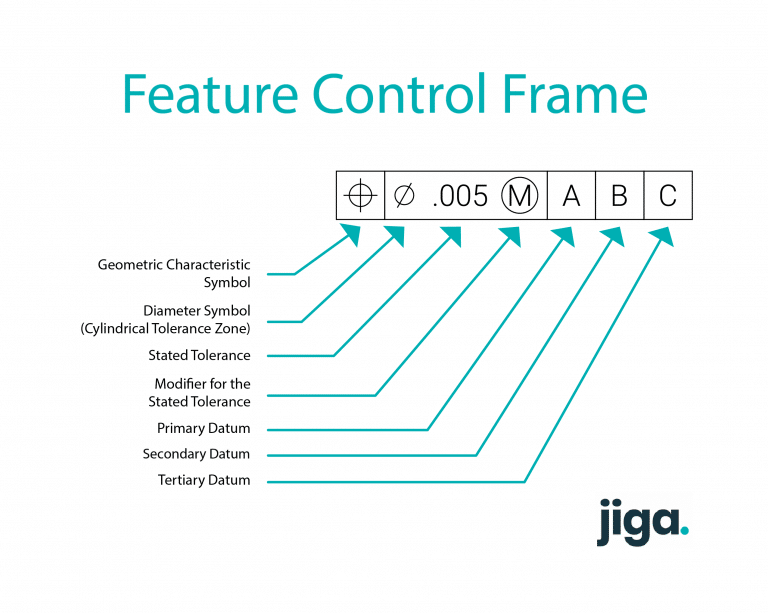
Feature Control Frame (FCF)
The FCF is the part of the design that contains the instructions and requirements for the feature to which it is attached. As you might expect from the name, the feature control frame controls the features.
Each feature control frame can only contain one instruction or requirement and if multiple instructions or requirements are required, then the design must contain multiple FCFs.
Each FCF is split up into sections that contain the following information:
- One of GD&T’s geometric characteristic symbols that specifies a requirement, such as this feature must be straight.
- The future tolerance for the future, which is always a total tolerance. This may be preceded by the diameter symbol,⌀, as in the image above, to represent a cylindrical-shaped zone such as the position of a hole.
It can also be followed by a Material Condition Modifier (MCM) to indicate that the feature has size. - The third section and the sections following it contain the required datum feature reference or references. These are arranged in order of precedence from right to left.

George B
CTO
"Hands-Down the Best Platform and Partner for Fast, Quality Parts"
Jiga is the best way to get the parts you need, when you need them.
How GD&T Works
GD&T is essentially a language for expressing the exact dimensions of a part and minimum and maximum acceptable tolerances.
The GD&T symbols are a quick and effective way of communicating complex information that would otherwise fill a design diagram with text clutter.
Essentially GD&T communicates both design specifications and design intent.
As an example, if you were designing a work surface for a kitchen, you might indicate a thickness tolerance of between 100mm and 120mm.
However, this information on its own could result in the surface of the countertop becoming waved in 20mm peaks and troughs, or becoming wedge-shaped with one end 20mm thicker than the other.
The inclusion of GD&T symbols prevents this by indicating that the design intent is for the part to be flat.
Do I Need to Use GD&T for Additive Manufacturing?
The short answer is yes.
While it might seem unnecessary to provide technical documentation with a full 3D model, it is important to remember that GD&T also provides the design intent along with the technical specifications, which a 3D model does not.
At its heart, GD&T is an unambiguous mathematical communication method of the tolerances your parts can have and still fit together.
Additive manufacturing might have changed how we produce parts, but it doesn’t remove the need for precise product design documentation.
Benefits of GD&T in Manufacturing
Proper GD&T is a vital part of complex machining and additive manufacturing and offers a number of significant material benefits, including:
Lowered costs – Effective GD&T greatly enhances the accuracy of designs by allowing for the appropriate tolerances.
In addition, the GD&T process often produces additional tolerances which help to increase the cost-effectiveness of a given project.
Essentially, GD&T removed two of the most common issues that occur between the design and manufacturing phases of any given product.
Inaccuracies leading to faulty or useless parts and overly strict tolerances that constrain manufacturing flexibility.
Accurate fulfillment – GD&T allows for the accurate statement of all design requirements without the need for huge reams of text.
Because all of the design requirements are made explicit through the GD&T process, designers can expect manufacturers to create parts that are accurate to all dimensional and tolerance specifications
Enhanced Communication – As a single simplified and unified design and manufacturing language, GD&T allows the communication of complex part designs across multiple stakeholders.
This means that different departments and different sections of the supply chain can align behind a shared and accurate interpretation of design.
Increased Flexibility – Since GD&T expresses a design intent, rather than just specific geometry. This allows for the widest range of tolerances to be utilized as long as they do not impact the functionality of the part.
This, in turn, results in greater flexibility of tolerances and therefore, greater manufacturing flexibility, helping to keep costs down.
Digitally Adaptable – GD&T is as useful when used in common 2D and 3D CAD design programs as it is when written onto graph paper.
Because of its universality, the differences between ASME and ISO notwithstanding, GD&T allows for easy design communication across different digital platforms and even between software and pen and paper.
