
Where a printer specification might assert ±0.2 mm linear tolerance, one service provider might warrant ±0.3% as a general 3 axis guide, while another provides separate X/Y and Z tolerances. Those numbers cannot reliably tell you the degree to which a 3D printed part will match its drawing.
For production-level additive manufacturing, the important question is not simply “How accurate is this 3D printing process?” It is:
Can this process repeatedly produce the critical features on this part, within their specified tolerances, and how will the supplier prove this?
That requires a chain of engineering decisions, clarified in this article.
Published tolerance figures are useful for process selection, but only as starting points. Production acceptance ultimately relies on the printed part, specified drawing notes, a qualified manufacturer, and an appropriate measurement basis.
What "tolerance" actually means in additive manufacturing
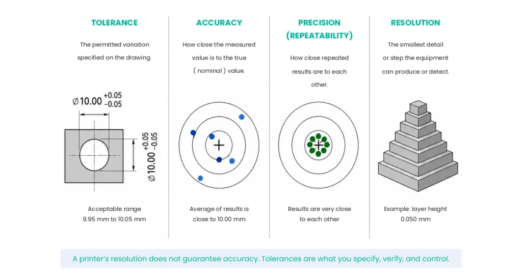
Four terms are frequently muddled together in discussions of 3D printing tolerances.
- Tolerance is the permitted dimensional or geometric variation specified in the design.
- Accuracy describes how closely the manufactured result approaches the nominal value.
- Precision or repeatability describes how consistently the process reproduces a result, over multiple parts.
- Resolution describes the smallest feature or incremental detail the equipment can theoretically produce or control.
Note, usefulness/completeness of the feature typically requires a size that’s a multiple of resolution, and considerable engineering judgement being applied by the designer.
A printer with a very small layer height therefore does not necessarily have correspondingly tight dimensional accuracy. A 50 µm layer does not mean the machine can hold ±50 µm on three axes on a finished component.
This aspect matters because the final geometry is affected by a complex process chain: Orientation, thermal history, material behavior, supports, cleaning, curing, heat treatment, depowdering, and secondary machining can all influence the finished dimensions. These are production variables that must be considered alongside nominal printer capability.
What tolerances can 3D printing actually hold?
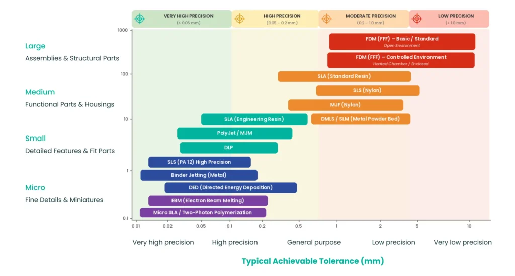
There is no single, overarching process-tolerance for FDM, SLA, SLS, MJF, or metal additive manufacturing.
Published figures vary substantially as suppliers use different equipment, materials, geometries, measurement bases, part sizes, operational methodologies, and definitions of capability. Some publish percentage-of-dimension tolerances, some provide a fixed minimum, and others specify tolerances according to axis.
A useful comparison is therefore a range of published capabilities, not a universal specification.
| Process | Representative Published Tolerance Guidance | Important Limitation |
|---|---|---|
| FDM/FFF | ±0.5% with ±0.5 mm lower limit for prototyping; industrial guidance as tight as ±0.15% with ±0.2 mm lower limit | Material, machine class, orientation and feature size matter strongly |
| SLA | Published values range from roughly ±0.2 mm/±0.5% to much tighter industrial values; some providers specify X/Y and Z separately | Post-cure and support removal influence final dimensions |
| SLS | Around ±0.3%, commonly with ±0.3 mm lower limit; other guidance uses fixed + percentage formulas | Thermal shrinkage and part placement matter |
| MJF | Approximately ±0.3%, often with a ±0.2–0.3 mm minimum; other providers publish fixed + percentage values | Thermal history and geometry affect accuracy |
| DMLS/metal AM | Published guidance ranges around ±0.1–0.2% or fixed + percentage formulas, frequently with different X/Y and Z values | Residual stress, heat treatment and post-machining can dominate final accuracy |
| PolyJet | Around ±0.1 mm-class to fixed + percentage formulations depending on provider | Material and geometry dependent |
| Carbon DLS | Published guidance around ±0.1%, with a minimum around ±0.1 mm | Machine/material/process-specific |
These figures reconcile the varied forms of vendor guidance, but should not be read as guaranteed production tolerances. The underlying published numbers differ substantially, even for notionally identical processes/equipment.
| Process | Technology | Typical Layer Thickness (µm) | Achievable Dimensional Tolerance (± mm) | Minimum Feature Size (mm) | ||
|---|---|---|---|---|---|---|
| Small Part (< 25 mm) |
Medium Part (25–100 mm) |
Large Part (> 100 mm) |
||||
| FDM (FFF) | Fused Deposition Modeling | 100–300 | ±0.30 | ±0.40 | ±0.60 | 0.8–1.5 |
| SLA | Stereolithography | 25–100 | ±0.08 | ±0.12 | ±0.20 | 0.2–0.5 |
| SLS | Selective Laser Sintering | 60–150 | ±0.20 | ±0.30 | ±0.40 | 0.6–1.0 |
| MJF | Multi Jet Fusion | 80–120 | ±0.20 | ±0.30 | ±0.40 | 0.5–0.8 |
| DMLS (SLM) | Direct Metal Laser Sintering | 20–60 | ±0.05 | ±0.10 | ±0.15 | 0.3–0.6 |
| PolyJet | PolyJet Photopolymer | 16–30 | ±0.05 | ±0.10 | ±0.15 | 0.2–0.5 |
What these numbers do not mean
A published ±0.2 mm machine capability doesn’t mean every part will emerge with every surface within ±0.2 mm of the CAD.
The headline fails to account for overall and local warping, orientation, material shrinkage in printing or heat treatment and more
It isn’t typically a tolerance the supplier will contractually commit to.
For production sourcing, ask the supplier what tolerance they’re comfortable committing to on the part, material, orientation, machine, and finished condition, rather than relying on the printer manufacturer’s headline accuracy.
Why published 3D printing tolerances disagree
Consider a 10 mm feature and a 400 mm feature.
A tolerance expressed only as ±0.3% gives:
- 10 x 0.003 = 0.03 mm
for the first feature and:
- 400 x 0.003 = 1.2 mm for the second.
But a supplier may instead specify:
- 0.3%, with a minimum of 0.3mm
The 10 mm feature tolerance would then be ±0.3 mm, not ±0.03 mm.
Other suppliers use formulations such as:
- A mm + B%
These approaches cannot be compared simply by putting their percentage figures against one another.
Axis also matters. Protolabs data, for example, provides different X/Y and Z values for SLA and DMLS, rather than treating the process as omnidirectional.
A credible tolerance discussion therefore needs to state the measurement basis alongside the number.
What drives tolerance variation?
Build orientation
Additive manufacturing is inherently directional, and often anisotropic in complex ways.
A cylindrical feature oriented vertically is created differently from the same feature lying horizontally. Layer stair-stepping, unsupported surfaces, support contact, shrinkage, and thermal gradients all change.
Consequently, the same CAD feature can produce different dimensional results depending on orientation.
Part size
Larger parts and thicker sections entail greater opportunity for thermal contraction consequences, warping, and percentage-based dimensional deviation.
This explains why fixed ±mm figures can be misleading, when applied to large parts, and percentage figures can be misleading, when applied to small precision features.
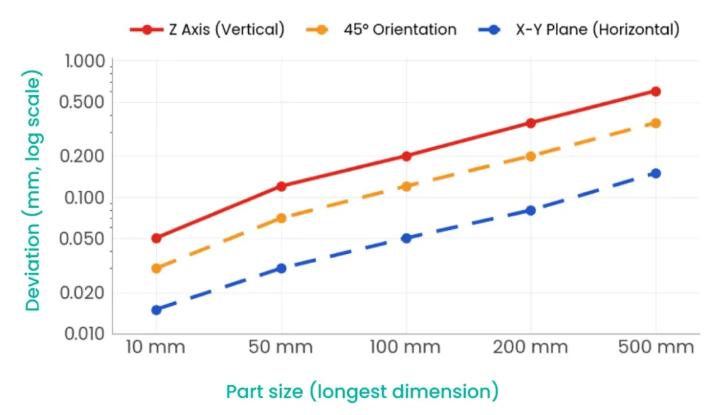
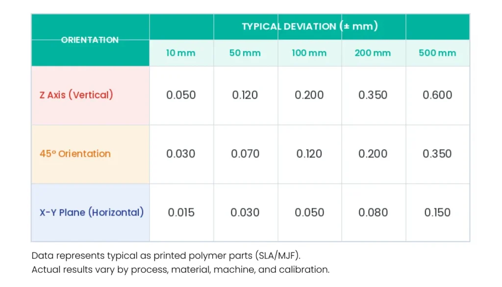
- X-Y accuracy is somewhat better than Z accuracy on most systems
- X-Y accuracy degrades towards the Z accuracy as surfaces angle from the horizontal
- Larger parts/features suffer increased cumulative error overall – this influences long features and measurements, while sub-features and short measurements retain LOCAL accuracy while suffering greater POSITIONAL error
Local accuracy vs. whole-part accuracy
A part can contain a bore that measures accurately while its overall structure is warped. Conversely, the outside envelope may be close to CAD while an unsupported internal hole is substantially distorted.
This distinction drives which inspection approach serves well. A caliper measurement across two surfaces says very little about whole-part shape, where a 3D scan may offer poor information at the small scale.
Polymer process effects
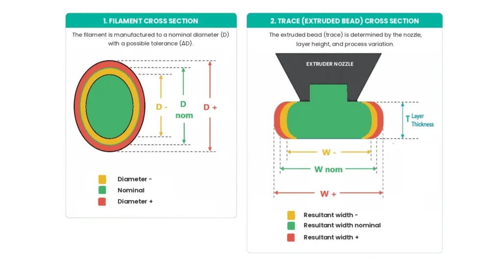
FDM accuracy can be affected by extrusion behavior, layer bonding, feedstock moisture content, material shrinkage, and the considerable anisotropy that varies with build orientation.
SLA is influenced by resin condition, support strategy, washing, and post-curing. Incomplete or excessive cure can alter dimensions in significant and unpredictable ways.
SLS and MJF depend heavily on thermal management. Polymer powder experiences significant shrinkage, which is compensated for during build preparation, but real results still depend on geometry and thermal history.
Powder refresh ratio and contamination are also production variables for powder-bed, polymer based processes.
Metal AM effects
Metal additive manufacturing introduces additional dimensional variables and complexities.
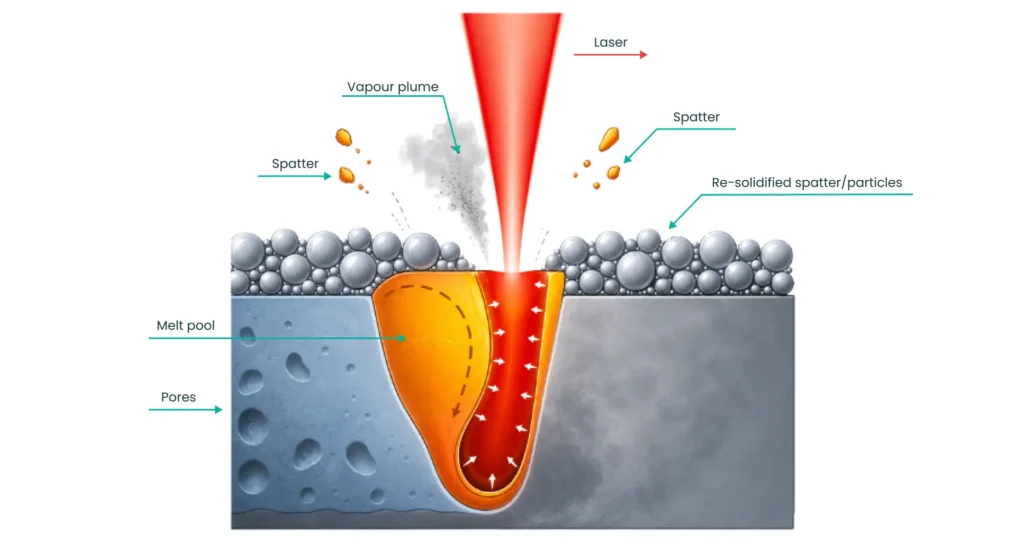
Residual thermal stress can distort the component during printing, post-print stress relief, and even removal from the build plate. Supports influence both heat transfer and structural restraint. Subsequent heat treatment and HIP (hot isostatic pressing) may cause further dimensional change.
For precise results beyond the print capability, a precise specification bore should be printed near-net and machined to ±0.05 mm after stress relief
Frequently, the hybrid approach provides a much more controllable production route.
How to specify AM tolerances on the drawing
Component drawings should specify the functional requirement of the finished component, rather than copying a printer’s advertised tolerance as a TYP guide.
Start by identifying critical features like datum and seal surfaces, bearings/dowel holes, and threads, and assembly-critical areas.
Noncritical geometry can then use suitably loose tolerances, and where necessary, tighter tolerances requiring hybrid processing can be clearly stated.
Establish useful datums
GD&T applies to additive parts as much as from any other manufacturing process, but useful annotation requires stable, measurable datum features.
A rough or irregular as-printed surface will typically be a poor datum for a precision feature. If the component requires tight positional control, it can be better to provide machinable datum pads or other deliberately created reference surfaces.
The process is print, post-process (heat treat), machine, and then inspect, rather than attempting to impose machining-level geometric control directly on unstable, as-printed surfaces/features.
ASME Y14.5 can provide the GD&T framework, while ISO/ASTM 52900 provides the appropriate AM terminology. Neither should be interpreted as a table of guaranteed AM process tolerances. ISO 2768 and ISO 286 are conventional-manufacturing standards that may be applied where appropriate, rather than highly apt AM capability standards.
Distinguish as-printed and finished dimensions
This is essential for hybrid parts.
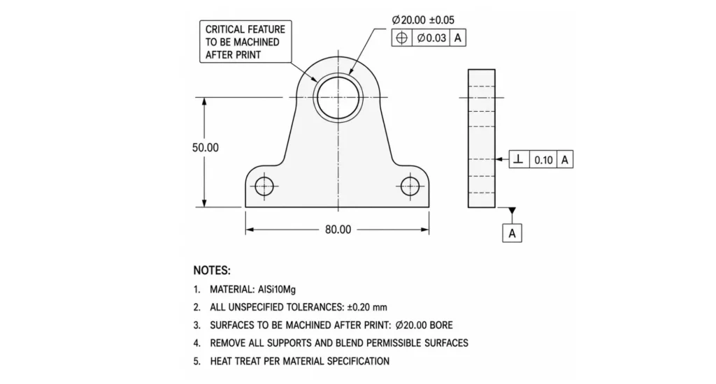
A critical bore might be specified as:
PRINT WITH MACHINING ALLOWANCE. MACHINE AFTER STRESS RELIEF.
The drawing then controls the final bore dimensions, using the required size, position, cylindricity, or fit.
Stock allowance must be intentional. A surface cannot be finish-machined reliably, if the printing process potentially presents insufficient material.
Likewise, excess allowance adds machining time and may render difficult internal geometry less accessible.
Treat holes carefully
Printed holes deserve close attention, as their geometry can be influenced by orientation, layer stepping, shrinkage, downskin behavior, and support strategy.
Where a hole accepts a precision bearing, dowel, seal, or shaft, printing near-net – followed by drilling, reaming, boring, or machining. This is often preferable to demanding an unnecessarily tight, as-printed diameter.
For defined engineering fits, the final machined feature can then use the appropriate ISO 286 or drawing-specific fit requirement without any AM reference or characterization.
How do you verify 3D printing tolerances?
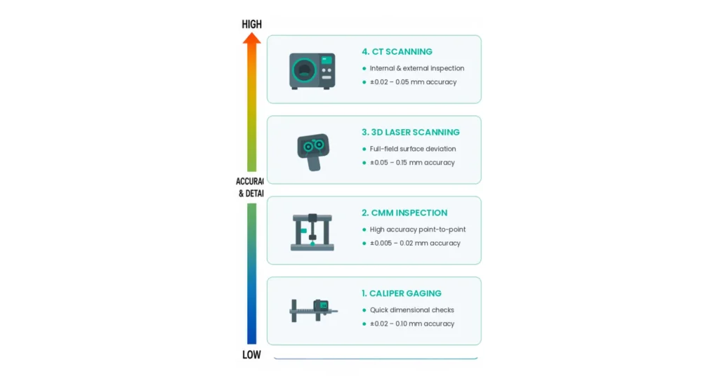
The inspection method will usually be derived from the geometry and tolerances being assessed. There is a simple progression from inexpensive, to sophisticated equipment, so a fit-for-purpose choice can save time and money.
Calipers and conventional gages
These are appropriate for accessible dimensions, and relatively relaxed tolerances.
Go/no-go gages can be particularly useful in production, where the functional question is simply whether a feature falls within its acceptance limits.
CMM
A coordinate measuring machine is appropriate for accurate feature location, datums, GD&T characteristics, bores, planes, and other accessible geometry.
It is additionally applicable where the inspection report must tie directly to drawing characteristics.
Laser or structured-light 3D scanning
Scanning is useful for large, or freeform components, where whole-part or regional deformation is important and potentially hard to characterize.
A scan-to-CAD deviation map can readily reveal bowing, twisting, local shrinkage, and areas systematically displaced from nominal geometry.
That provides an integrated overview which can offer considerably more information than measuring a few discrete CMM points.
CT inspection
Computed tomography is an extremely expensive choice, relevant for evaluating critical geometry that cannot be accessed physically.
It can enable inspection of internal channels and hidden features and, particularly in metal AM, can also support wall-internal defect analysis such as porosity
Dimensional CT and porosity inspection should not automatically be treated as the same test. Resolution and scan setup need to be matched to the inspection objectives.
Measurement capability matters too
A ±0.1 mm tolerance is not meaningfully controlled by a measurement system whose uncertainty or repeatability approaches ±0.1 mm.
Before calculating process capability, establish that the inspection system itself is capable of meaningfully resolving the potential errors being checked for.
That is where Gage repeatability and reproducibility (R&R) becomes important.
Gage R&R is a statistical tool used in Measurement Systems Analysis (MSA) to establish the level of variation in data caused by the measurement tool and the people using it, rather than actual differences in the parts.
From first article to production control
Passing one first article does not demonstrate long-term process capability.
For production AM, dimensional variation can occur for a range of build, supplier, and material reasons.
Once the measurement system is demonstrated to be suitable, Cp/Cpk or other statistical methods can assess repeatability.
But AM imposes a need for care here. Pooling results from varied machines, build orientations, and build positions into one Cpk number may conceal meaningful process differences.
For a critical application, capability can only be demonstrated for the qualified machine, parameter set, orientation, material, and post-processing route.
Witness coupons can support process monitoring, but they do not automatically prove the dimensions of the actual component. A tensile coupon demonstrates something different from a CMM report on a production bore.
Fitting AM tolerances into the quality system
For regulated or production applications, dimensional control must associate with traceability.
Depending on program requirements, records may include:
- build ID
- machine ID
- parameter-set revision
- material and powder/resin lot
- powder refresh information where relevant
- build orientation
- heat treatment and HIP records
- secondary machining route
- material certificates
- inspection reports
- certificates of conformance
- lot identification
FAI/AS9102, PPAP, AS9100, ISO 9001, and ISO 13485 are relevant quality-system contexts.
These should not be treated as universally mandatory, but as a toolkit with some potential utility.
AS9102 FAI applies where invoked by aerospace customer or contractual requirements. PPAP similarly depends on customer/program requirements, most commonly in automotive and related production supply chains.
Their significance here is the same: drawing requirements must flow into informative and measurable characteristics, inspection evidence, and traceable production records.
If production moves to another printer, facility, parameter set, or supplier, it’s imperative to determine that the qualification evidence remains valid, or it must be revised appropriately. For critical production parts, requalification may be required, avoiding the risk inherent in assuming that two machines of the same model produce interchangeable results.
Supplier approval checklist for AM tolerances
Sourcing across several AM processes and shops is where a single accountable supplier of record earns its place: someone owns these answers instead of leaving you to chase each shop.
Before awarding repeat production, ask the supplier:
- What tolerance will you commit to for this actual part/material/process?
- Which dimensions vary significantly with orientation?
- Which critical features should be machined after printing?
- How will each critical characteristic be inspected?
- Can you provide dimensional data from comparable production geometry?
- How are machine, build, material lot and parameter revision traced?
- How is build-to-build dimensional stability monitored?
- What changes trigger requalification?
No datasheet or supplier marketing content can really answer these questions.
The most relevant supplier capability is to repeatedly deliver finished parts conforming to the drawing, with objective evidence that they conform.
For buyers sourcing production AM across multiple processes and suppliers, this is also where accountability becomes valuable. A datasheet tolerance no shop will commit to, quoted through a black box, is the failure mode this avoids. Jiga is your custom manufacturing arm and supplier of record, owns the drawing requirement through to the manufacturing route, qualified supplier, inspection plan, documentation, and delivery. The objective, as with any production process, is reduced surprises at receiving inspection and a single, accountable party for parts arriving on time and on spec.
The production rule
The most useful 3D printing tolerance is the one the design requires, the route can repeatedly achieve, the supplier will commit to, and the inspection system can verify.
It is the tolerance that the design actually requires; that the selected manufacturing route can repeatedly achieve; that the supplier will commit to; and that the inspection system can objectively verify.
For noncritical geometry, that generally means accepting normal as-printed process variation.
For a bearing bore, sealing face, precision datum, or positional interface, the most appropriate answer may instead be to print near-net, establish stable datums, machine the critical feature, and inspect the finished result.
That is the shift from treating additive manufacturing as a printer-selection exercise to treating it as a production process. If you specify the finished requirement and control the process well, intention will match outcome
Frequently Asked Questions
What tolerances can 3D printing actually hold?
Published industrial guidance ranges from several tenths of a millimeter for processes such as FDM, SLS, and MJF to tighter values for some SLA and metal-AM applications. The achievable tolerance depends on feature size, material, orientation, machine, geometry, post-processing, and whether the dimension is as-printed or subsequently machined.
Which 3D printing process has the tightest tolerances?
SLA and some metal AM processes publish relatively tight dimensional capabilities, but comparing processes by a single number is generally misleading. Build orientation, part size, material, post-processing, and measurement basis must also be considered.
How do you specify a tolerance for a 3D printed part on a drawing?
Specify the required finished feature using normal dimensional and GD&T practices. Identify critical datums and features, distinguish as-printed from machined surfaces, and explicitly call out post-print machining where the printing process alone cannot reliably meet the requirement.
How do you verify that a 3D printed part meets tolerance?
Use an inspection method suited to the feature: conventional gaging for simple dimensions, CMM for precision features and GD&T, 3D scanning for whole-part shape and warpage, and CT where important geometry is internal or inaccessible. The measurement system must possess adequate capability, relative to the tolerance.
Why are my 3D printed parts out of tolerance?
Common causes include shrinkage, thermal distortion, build orientation, part size, support strategy, material condition, post-cure, depowdering, support removal, heat treatment, residual stress, and inadequate process compensation. The cause should be identified, before simply widening the drawing tolerance.