
Anodizing changes dimensions, more than some processes such as alodining, but less than others such as powder coat. The core engineering problem is deciding how much change your particular feature can tolerate, where that change will occur, and how you will prove the finished part still conforms to the functional and assembly requirements.
Outside dimensions generally grow as the anodic layer develops. Internal dimensions such as bores become smaller. Threads, precision fits, datum surfaces and sealing interfaces can be particularly sensitive, because the coating may be developing on more than one functional surface.
For loose-tolerance components, that dimensional change will generally be insignificant. For a bearing bore, sliding fit or precision shaft, it can consume a substantial part of the available tolerance.
The mass production solution is not simply to shrink the CAD in critical areas by a standard anodize allowance. A more reliable approach accounts for machining variation, pretreatment, coating thickness and its variation, alloy and geometry, masking, measurement uncertainty, and the final acceptance requirement.
An appropriate approach is to machine and measure the feature before pretreatment and anodizing, then measure the coating thickness and finished feature to verify final conformity. The resulting measurements can then establish and control the pre-anodize machining target.
MIL-PRF-8625 is an applicable standard, according to the U.S. Defense Logistics Agency’s ASSIST database, with the active document dated November 23, 2020. It covers six anodic coating types and two classes for Aluminum and Aluminum alloys.
How much does anodizing change a dimension?
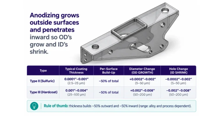
Anodizing develops both outward from the original surface and into the Aluminum substrate.
It is wrong to assume automatically that the original surface grows entirely outward by the treatment thickness. Some of that oxide deposits below the original surface.
Sources report various approximate relationships, including 50/50, 45/55 and 33/67 penetration-to-build-up interpretations. The relationship varies with alloy and process, and can only be ascertained by micrograph of a supplier sample.
For tolerance analysis, it is appropriate to distinguish three quantities:
- Total oxide thickness
- Penetration
- Build-up.
Only the last quantity controls the scale and effect of the dimensional change.
OD/ID changes
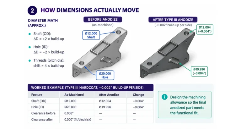
For a cylindrical shaft with radial build-up b on each side:
Finished OD ≈ pre-anodize OD + 2b
For a bore:
Finished ID ≈ pre-anodize ID − 2b
The same basic logic applies to two opposed coated surfaces in a slot, or other internal feature.
4 times the build-up is widely reported as a useful pitch-diameter effect for threads, but this should be treated as a design guideline rather than a substitute for processor-specific requirements, section-micrograph evaluation, and validation.
Type II versus Type III is significant
Wide reporting provides practical working ranges:
| Process | Typical Thickness Range Cited in Brief | Dimensional Significance |
|---|---|---|
| Type II sulfuric anodize | ~0.0001 to 0.001 in. (2.5–25 µm) total | Often modest, but significant on close fits |
| Type III hardcoat | ~0.001 to 0.004 in. (25–100 µm) | Can materially alter precision fits |
| Common Type III design point | ~0.002 in. (50 µm) | Requires deliberate dimensional planning |
These should be treated as engineering reference ranges, rather than universal process outputs. Actual requirements come from the applicable drawing, specification and qualified process.
MIL-PRF-8625 identifies Type II as conventional sulfuric-acid anodizing and Type III as hard anodic coating.
It also covers Types I, IB, IC and IIB, so don’t describe MIL-PRF-8625 as though it covers only the more commonly discussed Type II and Type III processes.
The tolerance problem is bigger than coating thickness
A common calculation looks like this:
Where the expected anodize build-up = 0.001 in. per side, machine a bore 0.002 in. oversize.
That may be a useful starting estimate and may suffice for relaxed fits, but it is not a complete tolerance analysis for high-precision parts.
The finished dimension is affected by more than nominal coating thickness.
The finished dimension reflects the machined size, any dimensional change during pretreatment, and the subsequent anodizing build-up. Each stage introduces some variation, with measurement uncertainty added at inspection.
The drawing tolerance belongs to the finished component unless the product definition explicitly states otherwise.
Follow one real part through the process
Consider a 7075-T6 Aluminum bearing housing.
The part contains a precision bearing bore and an external locating diameter. It has a machined mounting datum and threaded mounting holes. Lower precision applies to noncritical external surfaces, and an electrical grounding location
Assume the finished bearing bore must be:
Ø25.000 ±0.025 mm after anodizing
That implies an acceptable finished range of:
24.975 to 25.025 mm
You have to decide how that bore will be manufactured.
There are three broad strategies:
Strategy 1: Anodize the bore and compensate during machining
Machine the bore oversize so that expected anodic build-up brings it toward its finished target.
Strategy 2: Mask the bore
Machine the bore directly to the required final dimension, and prevent anodizing from developing on the functional surface.
This can work well for bearing seats and other precision interfaces, although masking introduces practical issues with edge definition, bleed, geometry and handling.
The unprotected surface may pose a galvanic corrosion risk, in wet environments, though this can be moderated by using a fitting compound that seals the contact surfaces.
Strategy 3: Anodize and finish-machine the bore afterward
Set aside concerns about suitable material or coating condition, by subsequent precision machining to final size, where technically appropriate.
This can provide excellent dimensional control, but removes anodic protection from the subsequently machined surface and adds a potentially costly machining process, after ‘finishing’.
The choice depends on the functional requirement.
Calculate a tolerance window, not just a nominal allowance
Suppose the anodizer expects a nominal radial build-up of 0.025 mm on the bore surface.
The simple calculation establishes a nominal target size:
Required pre-anodize bore = 25.000 + 2(0.025) = 25.050 mm
It does not ensure that production will stay inside the finished 24.975 to 25.025 mm acceptance window, however.
As an illustrative engineering example, FAI validated production shows ongoing data that radial build-up can vary between 0.020 and 0.030 mm.
A pre-anodize bore of 25.050 mm could then theoretically finish between approximately:
25.050 − 2(0.020) = 25.010 mm
and
25.050 − 2(0.030) = 24.990 mm
Both results fall within the 24.975 to 25.025 mm finished tolerance.
But it is also necessary to consider allowance for machining variation.
If the pre-anodize machining process itself varies ±0.015 mm, the combined worst-case window becomes substantially wider.
The values above are deliberately illustrative, not MIL-PRF-8625 requirements. Production allowances should be established from the specified coating requirement, processor capability/self reporting, and validation measurements from pre-production samples.
Think in three dimensional states
For genuinely tight fits, three dimensional states may matter: the size leaving the CNC operation, the size after pretreatment, and the final size after anodizing.
Cleaning, caustic etching and other pretreatment processes can alter the substrate before the anodic layer develops.
Where the drawing specifies the requirement after finishing, it is the final anodized dimension that determines acceptance.
How to specify anodizing on the drawing
The anodizer should not have to infer design intent from a generic note saying:
HARD ANODIZE BLACK.
A production drawing should establish the applicable finish requirements, with enough precision to remove ambiguity.
Depending on the program, this may include a drawing note such as:
ANODIZE PER MIL-PRF-8625, TYPE III, CLASS 1
or other applicable type/class required by the design.
The exact callout must reflect the relevant specification, and customer requirements, rather than being copied blindly from another drawing.
MIL-PRF-8625F with Amendment 2 identifies Class 1 as non-dyed and Class 2 as dyed. It identifies Type III as hard anodic coating.
But the specification designation alone does not communicate every dimensional requirement.
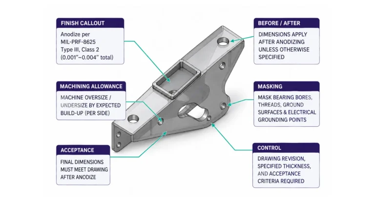
For tight-tolerance components, state clearly on the drawing whether dimensions apply before or after anodizing, along with any required coating thickness. Identify the surfaces that need to be masked and those that must receive the coating, and define the finished dimensional acceptance criteria.
Specify critical functional interfaces and applicable surface-finish requirements too, along with any inspection or certification requirements and the relevant drawing revision.
The annotation AFTER ANODIZING can eliminate otherwise surprisingly expensive ambiguity.
Don't make the processor decide which dimension matters
Suppose the bearing-housing drawing shows Ø25.000 ±0.025, but doesn’t clearly state whether the dimension applies before or after hardcoat.
The machinist may hold 25.000 mm.
The anodizer may then correctly apply the specified coating.
The resulting bore can be undersized, even though both suppliers performed their individual operations correctly.
In this case, the drawing failed as a communication tool
For critical dimensions, communicate the required finished condition explicitly.
Should you machine before or after anodizing?
Geometry is normally established before anodizing, followed by the specified finishing process.
The surface question is whether a specific functional feature should be coated and compensated, masked, or finished after anodizing.
Coat and compensate when the functional surface benefits from anodic protection and the combined machining/anodizing process can reliably hold the finished requirement.
Mask when dimensional, electrical, bearing, sealing or interface requirements make the anodic layer undesirable on that surface. Recognize that masking is manual, adds cost and introduces bleed risk.
Finish after anodizing when the tolerance cannot reliably accommodate coating variation and exposing substrate on the finished surface is acceptable to the design.
The choice is yours as the engineer, not an assumption made independently by the CNC shop or anodizer.
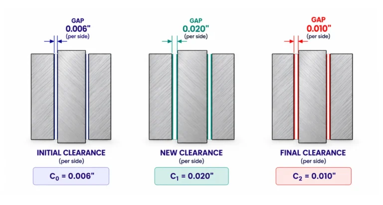
Fits need a clearance budget
Matched components make the dimensional effect particularly obvious.
Consider an anodized shaft running in an anodized bore.
Shaft OD increases by approximately 2 x the radial buildup, while bore ID decreases similarly
The available diametral clearance can therefore decrease by approximately 4 x the buildup, when both mating surfaces receive equivalent build-up.
This is why a sliding assembly that works perfectly before finishing can bind afterward.
A Type III example with around 0.002 in. coating thickness presents roughly 0.004 in. total movement across an uncompensated matched fit, under its assumed build-up relationship.
For design work, however, don’t calculate only nominal clearance. Calculate minimum and maximum finished clearance, using the allowable shaft size, bore size and validated coating variation.
That tells you whether the fit still functions at the tolerance extremes.
Threads deserve separate treatment
Threads amplify the practical consequences of coating.
A useful rule-of-thumb applies approximately four times the per-surface build-up, as an effect on thread pitch diameter. But thread geometry is more complicated than a plain cylindrical surface.
For tight or functionally important threaded interfaces, options can include masking, establishing a process-specific pre-anodize allowance, appropriate pre-process thread sizing, or controlled post-process treatment where permitted.
The essential production requirement is that the finished, threaded feature passes the specified acceptance criteria. However, nothing replaces thread gauging.
GD&T does not disappear when the coating goes on
Anodizing discussions often concentrate entirely on diameter.
The finished coating can also matter to geometric requirements involving flatness, profile and perpendicularity of surfaces; runout of shafts/bores; and datum/nating surfaces
Consider the bearing housing again.
If the finished anodized mounting face establishes datum A, inspection needs to evaluate the relevant finished surface in accordance with the drawing.
If that surface is masked, the datum is being established on an uncoated substrate instead.
So consider the relationship between coating strategy and the datum reference frame, rather than treating finishing as an operation that happens after all dimensional decisions are made.
Surface finish can matter as much as size
A bearing seat, seal interface or sliding surface can meet its diameter requirement, while failing functionally because its surface condition is unsuitable.
Hard anodizing changes the nature of the surface itself. Where function depends on both geometry and surface condition, specify both.
A finished dimension such as:
Ø25.000 ±0.025 mm
does not communicate an allowable roughness.
Conversely, an RA requirement does not control diameter.
Corners and edges need deliberate design
Sharp geometry can complicate precision anodizing, through highly localized coating behaviour, fragile hardcoat edges, interference at mating corners, and poorly defined masking boundaries.
It can also make subsequent measurements less consistent. A controlled edge break or radius can make the finishing process more predictable, provided it does not compromise the functional geometry.
Deep bores, blind holes and complex internal geometry also deserve careful consideration. Do not assume that a thickness measurement taken on an easy external face necessarily proves identical coating behavior everywhere, on a geometrically complex and involute component.
Alloy matters
6061, 7075, 2xxx alloys and high-Silicon Aluminum castings should not be assumed to respond identically to anodic coating.
There is therefore no universal rule that hardcoat grow every surface by 0.001 in.
Anodizing type, alloy, pretreatment, process conditions and geometry all influence the end result.
For repeat production, the actual processor’s demonstrated results on the specified alloy and geometry are more valuable than a generic guide allowance.
How to verify anodize thickness
Coating thickness and finished dimensional conformity are two different acceptance questions.
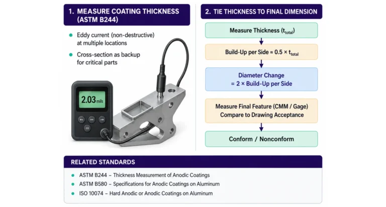
ASTM B244 covers nondestructive eddy-current measurement of nonconductive coatings on nonmagnetic base metals and is particularly applicable to anodic coatings on Aluminum. ASTM currently identifies B244-09(2021) as the active version, in its revision listing.
An eddy-current instrument can therefore provide evidence about anodic coating thickness.
But suppose the coating measures exactly as specified.
That does not automatically validate that our Ø25.000 ±0.025 mm bearing bore is acceptable. It still needs control of the bore.
Verification begins with measuring the coating thickness and determining its effect on the relevant dimensions. The finished feature is then measured and compared with the acceptance limits specified on the drawing.
Measure where it matters
Coating-thickness measurement also requires consideration of location.
A measurement on a broad external face may be convenient and repeatable. The critical dimension, however, might be a bore, slot or other internal feature where the coating process is less effective due to concentration or field variations.
The assumption that one convenient thickness reading completely characterizes every surface on a complex component is therefore hazardous
For critical work, establish:
- required measurement locations
- number of measurements
- sampling frequency
- acceptance criteria
- instrument and method
- who records the result
- how the measurement is linked to the production lot
ASTM B244 also notes that substrate conductivity matters to instrument calibration, reinforcing that eddy-current measurement is a controlled assessment process, rather than simply touching a probe to the component.
Measurement capability matters on tight tolerances
Suppose the finished tolerance is ±0.010 mm.
A measurement system with uncertainty approaching the same magnitude cannot provide convincing evidence of conformity.
The inspection method therefore needs to be appropriate to the required tolerance.
Depending on the feature, verification might use:
- micrometer
- bore gauge
- plug or thread gauge
- CMM
- profilometer
- suitable coating-thickness instrument
The instrument should have a current calibration certificate, and the measurement strategy must be appropriate to the geometry and acceptance requirement.
Temperature also becomes relevant as tolerances tighten. Aluminum has relatively high thermal expansion, so precision measurements should be made under appropriate controlled conditions, when dimensional uncertainty from temperature becomes significant.
A tight tolerance requires a measurement system capable of resolving an order of magnitude closer precision than the target, for high reliability.
Establish the machining target from production evidence
For repeat production, establish the machining target from actual parts. Record the critical dimensions before finishing, anodize the part using the intended production alloy, pretreatment, coating specification and processor, then record coating thickness and measure the same features again.
Comparing the before-and-after measurements establishes the actual process shift. If that shift proves repeatable, the pre-anodizing machining target can be adjusted accordingly.
Control variation, not just the first part
A successful first article proves one part can be made right, not that the process will not drift.
For a high-volume, tight-tolerance bore, record both the pre-anodizing dimension and finished dimension over an extended production run.
That can help distinguish where variation originates, in the coating, or in prior stages
For sufficiently important characteristics and production volumes, statistical process-control methods can then be applied to the relevant variables. The goal is to keep the process centred sufficiently far from that limit. This allows minor variations to occur without disrupting output.
First Article Inspection and production evidence
For aerospace work where AS9102 is flowed down, First Article Inspection can provide formal evidence connecting product definition to the produced part.
The current SAE revision is AS9102C, revised June 28, 2023. It establishes requirements for performing and documenting FAI, and explicitly states that its requirements complement customer and applicable statutory/regulatory requirements.
For the bearing housing, the FAI package can provide a clear link between the drawing requirements, anodizing requirements, material and process certifications, finished dimensional results, and characteristic accountability.
The evidence should demonstrate that the specified process was applied and that the resulting finished component meets its product requirements.
Nadcap and anodizing
For aerospace programs, customer requirements may also require the anodizing processor to hold the appropriate Nadcap chemical-processing accreditation.
Nadcap is managed by the Performance Review Institute and applies accreditation to defined aerospace critical processes and products. PRI specifically includes anodizing within its chemical-processing knowledge and qualification framework.
Nadcap accreditation and MIL-PRF-8625 compliance answer different questions.
- MIL-PRF-8625 establishes coating requirements.
- Nadcap concerns the processor’s accredited critical-process system where required by the aerospace customer or program.
Neither replaces dimensional acceptance against the drawing.
Traceability should connect the coating to the physical part
For controlled production, the documentation should provide traceability from the material lot through the CNC work order and pre-anodize inspection to the anodizing batch. It should then link the coating certificate and thickness record to the final dimensional inspection, FAI or PPAP evidence, Certificate of Conformance (CoC), and ultimately the shipped lot.
This allows a later investigation to answer useful questions:
- Which material lot was involved?
- Which anodize batch processed the parts?
- What thickness was recorded?
- What were the final bore measurements?
- Which parts shipped in that lot?
A folder containing poorly organized certificates is not traceable. The records have to connect to the physical product.
Rework needs to be planned before a batch fails
One particularly important issue with tight-tolerance anodized parts is rework.
Suppose the finished bearing bore is undersized.
One proposed solution might be to strip the coating and anodize the part again.
That should not be treated as a dimensional reset.
Removing an anodic coating can affect the underlying material and therefore the subsequent geometry. Reprocessing may also be restricted by drawing, customer or process requirements.
Another possibility is post-process machining, but that removes anodic protection from the affected surface.
A concession may sometimes be possible, but only through the appropriate engineering and quality authorization.
The acceptable methodology should be established through the applicable engineering and quality system, not improvised by the finishing supplier.
Supplier changes can change your dimensional result
After 5,000 acceptable bearing housings have been delivered, the purchasing team then moves the job to another qualified processor.
Both processors may be qualified, but their process behaviours differ, within the allowed requirements. Do not automatically assume it transfers unaltered to the new.
The same caution applies to:
- alloy or material-source changes
- pretreatment changes
- anodize process changes
- masking changes
- manufacturing location changes
- significant geometry revisions
For tight fits, supplier change control is part of dimensional control.
Common failure modes and how to prevent them
| Failure | Likely Mechanism | Better Control |
|---|---|---|
| Bearing bore undersize | Coating growth not allowed for | Compensate, mask or post-finish |
| Shaft oversize | OD build-up ignored | Establish pre-anodize target |
| Sliding fit binds | Both mating surfaces coated | Calculate complete clearance stack |
| Thread will not gauge | Thread coating effect ignored | Mask/allow/verify as specified |
| Part passed before anodize but fails afterward | Wrong acceptance stage | State AFTER ANODIZE |
| Finished size inconsistent | Coating/process variation | Validate and monitor processor |
| Local interference at corner | Edge/corner coating behaviour | Appropriate edge design |
| Ground point electrically isolated | Anodic coating is insulating | Mask specified contact area |
| Coating thickness passes but dimension fails | Thickness treated as dimensional acceptance | Measure both |
| Re-anodized part remains out of tolerance | Substrate change during stripping/reprocessing | Engineering review before rework |
Supplier approval checklist for tight-tolerance anodized parts
Before production, confirm:
- The processor can meet the specified anodize type, class and coating standards/requirements, and approvals are current.
- Alloy and material conditions are identified.
- Critical finished dimensions are explicitly identified as before- or after-anodizing.
- Masked surfaces are clearly defined.
- Pre-anodize machining targets are controlled.
- Pretreatment effects have been considered where tolerances warrant it.
- Coating-thickness measurement method and locations are defined.
- Final dimensional inspection methods are appropriate to the tolerances.
- Lot traceability is maintained.
- Coating records and certificates are supplied, and FAI/PPAP requirements are complied with.
For a tight-tolerance anodized part, you need one point of accountability across the drawing, CNC supplier, qualified finishing source, inspection, and documentation. With Jiga as your supplier of record, someone owns that outcome, so the finished part comes back dimensionally correct and audit-ready, delivered on time and on spec.
The practical rule for anodizing tight-tolerance parts
Given the allowable variation in machining, pretreatment and anodizing, what pre-process target will reliably produce a conforming finished dimension?
For the bearing housing, that means defining the final bore first.
Then work backward, from finished tolerance. After the first parts are produced, work forward again, from the machined part size
That closed loop is what keeps a tolerance from becoming an argument between the machine shop and anodizer, after the parts fail inspection.
For the bearing housing, start with the required finished bore and work backward to establish the machining target. Once production parts are available, measured pre- and post-anodize dimensions provide the evidence needed to refine that target.
Done right, the process produces a bore within tolerance, supporting the machine shop and anodizer in delivering reliability.
Frequently Asked Questions
Does anodizing change tight tolerances?
Yes. Anodizing can increase outside dimensions and reduce inside dimensions because part of the anodic layer builds outward from the original aluminum surface. On diameters, dimensional change occurs on two opposed surfaces, so even relatively small radial build-up can materially affect a tight fit.
How much does a Type III hardcoat add to dimensions?
Approximately 0.001 to 0.004 in. (25 to 100 µm) total coating thickness is a useful Type III range, with approximately 0.002 in. (50 µm) as a common design reference. The actual movement of the original surface is the outward build-up portion of that coating, not automatically the complete oxide thickness.
Should dimensions be specified before or after anodizing?
For a functionally important finished feature, state the intended condition explicitly. If a bearing bore must be Ø25.000 ±0.025 mm on the delivered component, identify that requirement as applying after anodizing.
How do I keep press fits in tolerance after anodizing?
Calculate the complete fit, rather than looking at one component in isolation. Account for shaft growth, bore shrinkage, machining tolerances and coating variation, then evaluate minimum and maximum finished clearance or interference.
How do I keep threaded holes from binding?
Treat threads as a specific finishing problem, rather than applying plain-bore arithmetic. Establish the required finished thread acceptance, determine the permitted coating/masking strategy with the processor, and verify the finished feature using the appropriate thread gauge or inspection method.
How is anodize thickness verified?
ASTM B244 provides an eddy-current method for nondestructively measuring nonconductive coating thickness and is particularly useful for anodic coatings on aluminum.