
A supplier runs the first article as climb milling, gets it signed off, then quietly switches to conventional milling on the production lot to stretch a worn cutter. Nobody flags the change. The out-of-spec surface finish surfaces at receiving, weeks later, on parts your build schedule already depends on.
That is the real lesson underneath the mechanics. Cut direction is a parameter you specify, prove out, lock, and audit. It belongs in the process definition and stays there, rather than riding on an operator’s judgment on a production run.
In climb milling, cutter rotation and feed act in the same direction at the cutting interface. The tooth enters at relatively high chip thickness and leaves as the chip thins toward zero. Conventional, or up milling, reverses that progression: the tooth enters at very low chip thickness and the chip becomes thicker as the cut develops. These differences affect cutting forces, heat, surface finish, tool wear and the tendency of some materials to work-harden.

In production, the choice comes down to which method will hold the required geometry and surface condition on the actual machine, fixture, material and tooling.
The drawing defines the finished component. The machining process determines how the supplier achieves it. Where cutting direction or another machining parameter has a demonstrated effect on conformity, it can become part of the controlled production process.
Climb milling and conventional milling: The basic mechanics
The distinction is easiest to see at the cutter-to-workpiece interface.
Climb milling
In climb milling:
- cutter rotation at the cutting interface acts in the same direction as feed
- chip thickness starts relatively high
- chip thickness reduces toward zero as the tooth exits
- in a typical peripheral cut, the resultant force has a component toward the work support
Conventional milling
In conventional milling:
- cutter rotation at the cutting interface opposes feed
- chip thickness starts near zero
- chip thickness increases through the cut
- in a typical peripheral cut, the resultant force has a greater lifting component
The chip-thickness progression accounts for much of the practical difference. Climb milling generally involves less risk of rubbing at entry and often gives lower heat, reduced wear and a better finish. In conventional milling, the edge enters at very low chip thickness and can rub or burnish, before it starts cutting effectively.
Actual force direction depends on radial engagement, cutter helix, toolpath, part geometry and fixture orientation. On a more rigid CNC machine, the normal force and chip-formation characteristics usually favor climb milling.
Chip thickness is the real starting point
An end mill does not remove a strip of constant thickness. Chip thickness changes continuously as each flute passes through the engagement zone. The edge cuts most effectively once it is forming a chip rather than potentially rubbing against the surface.
In conventional milling, the edge enters at very low theoretical chip thickness. Some rubbing or burnishing can occur, before effective shearing begins, adding heat and causing considerable difficulty in work-hardening materials. Climb milling starts with a substantial chip and this progressively diminishes toward the cutter disengagement.
Other variables have to be considered alongside cut direction: radial engagement ae, axial depth ap, cutter engagement angle, feed per tooth, cutting speed, cutter diameter and geometry, flute count, tool stick-out, holder and fixture stiffness, entry and exit strategy, coolant or air delivery, chip evacuation and machine dynamics.
Radial and axial engagement change the result
Radial engagement is central to the comparison. Low radial engagement commonly suits climb milling, while high engagement changes both the force system and chip formation enough to justify testing other strategies, in some applications. There is no universal engagement threshold at which one method automatically becomes preferable.
Axial engagement changes the mechanical condition as well. A 12 mm end mill cutting 0.5 mm deep is not behaving the same when engaged 20 mm axially into a wall, even at the same radial stepover.
This becomes particularly important in high-efficiency machining, where substantial axial depth is combined with relatively small radial engagement.
Cutter engagement angle
Cutter engagement angle is the angular portion of the tool circumference in contact with the workpiece.
A light peripheral finishing cut may engage only a small part of the cutter. The same tool entering an internal pocket corner can suddenly engage a much larger arc. Cutting force, spindle load, heat generation, chip evacuation, cutter deflection and vibration all change accordingly.
Two operations described as climb milling can consequently impose quite divergent loading scenarios on the cutter, part, and spindle.
Improving CAM changes the comparison
Rapidly developing CAM approaches make the simple climb-versus-conventional designation less informative, on its own. A peripheral pass can have a fairly predictable engagement condition, while a full-width slot, pocket corner or abrupt change in toolpath can increase engagement sharply.
Adaptive and trochoidal paths are intended to limit these changes. Cutter engagement angle and chip thickness vary as the tool moves through the geometry, and the adaptive CAM path is used to keep radial engagement within a restricted range.
A climb-milled path can still overload a cutter, if it drives abruptly into a corner. An adaptive path through the same geometry can produce a much more consistent load.
In current approaches to roughing, engagement often matters more than the nominal cutting direction .
Full-width slotting
Full-width slotting needs separate consideration. At approximately 100% radial engagement, the cutter is engaged on both sides of the slot. The cutting edges therefore experience climb conditions on one side and conventional conditions on the other.
Tool loading, heat and chip evacuation can become more important than the climb/conventional label.
Trochoidal or adaptive slotting avoids continuous full-width engagement by using a smaller radial cut and a looping or dynamically adjusted path. This can improve chip evacuation and reduce large variations in cutter loading.


Surface finish, accuracy and tool life
These are all significant factors, when selecting the machining strategy.
Surface finish
Climb milling usually gives a better finish when the setup is stable. The edge starts by forming a heavy chip, and unloads toward exit, whereas conventional milling can rub before effective chip formation begins.
This chip-certainty advantage can disappear when deflection becomes the controlling factor. Cutter deflection acts differently relative to the finished surface in climb and conventional milling. On thin or flexible features, a conventional finishing pass can sometimes hold profile more accurately even if climb milling would otherwise be preferred.
Thin-wall example
Consider a machined aluminum enclosure with a nominal wall thickness of 3.00 ±0.05 mm
The CAM system can entail the correct nominal geometry, while the machined wall develops taper or retains excess stock because the cutter deflects under load.
Reversing the cutting direction changes the direction of cutter deflection relative to the finished wall.
Before changing the program, it is worth checking radial finishing allowance, axial engagement, cutter diameter and stick-out, holder rigidity, wall support, fixture stiffness, feed per tooth, cutter geometry and machine dynamics.
The solution may be a smaller radial finishing allowance, shorter tool, additional support, different cutting direction or a controlled spring pass. The appropriate choice is the one that produces the required measured wall profile.

Tool life and heat
Climb milling often lessens rubbing, reducing heat and wear, although the effect of cutting direction can be outweighed by other process conditions.
Compare two climb-milling operations.
Process A
- low radial engagement
- stable chip thickness
- good evacuation
- rigid toolholder
- short cutter stick-out
Process B
- high radial engagement
- intermittent corner overload
- poor evacuation
- excessive stick-out
- unstable fixture
Both are climb milling. Their tool-life results could still be very different.
Built-up edge (BUE) introduces another complication. In Aluminum and some stainless-steel cutting conditions, BUE can dominate finish and dimensional behavior. Cutting speed, lubrication, edge condition and chip evacuation may have a greater effect than changing milling direction.
Percentage claims for improved tool life should therefore be treated as application-specific, unless the cutting conditions and supporting test data are known.
Work-hardening materials
Austenitic stainless steels, Nickel alloys and similar materials require particular attention to minimum chip thickness.
If an edge repeatedly rubs instead of cutting, the surface can work-harden severely. The next tooth then encounters harder material, increasing cutting force, heat, and tool wear.
The edge needs to stay below the affected layer rather than repeatedly rubbing across it. Constant-engagement and trochoidal strategies can help by maintaining effective chip formation through changing geometry.
Machine capability and backflash
Backlash is the traditional reason for avoiding climb milling on older machines.
During climb milling, the cutting force can pull the table into the cutter. If there is appreciable lost motion (slack) in the feed system, the table can move suddenly, juddering as the backlash is taken up and released.
Consider a machine with:
- programmed chip load = 0.05 mm/tooth
- machine backlash = 0.20 mm
The uncontrolled movement is four times the intended chip load. Severe impact loading or cutter damage is likely.
Modern CNC machining centers normally use ballscrews, preload and closed-loop control systems that make climb milling practical. Older manual machines and worn equipment require more caution.
Machine condition involves more than backlash. Ballscrew preload, servo following error, axis reversal error, spindle runout, thermal growth, structural stiffness, vibration and fixture compliance can all affect the finished part.
ISO 230-2 positioning checks and ISO 230-4 circular-interpolation testing may be relevant, alongside dial-indicator backlash checks and ballbar testing.
Rigidity is a system property
Even a rigid five-axis machining center can produce a deflection problem because the complete cutting system extends beyond the machine structure:
- machine
- spindle
- holder
- cutter
- workpiece
- fixture
- table
can all add to deflection and vibration risks
The least rigid element in this chain will tend to determine the result.
Radial and axial engagement, cutter geometry, stick-out, holder, workholding, cutting speed, feed, entry method and material condition determine the actual cutting load and the system’s response to it.
A long end mill in a marginal holder cutting a thin unsupported wall remains a flexible system regardless of the rigidity of the machine operating it.
Workholding and force direction
Basic diagrams show climb milling pushing the workpiece toward the table and conventional milling tending to lift it. Real fixtures are three-dimensional, and the force vector needs to be considered relative to clamp locations, support points, thin walls, ribs, vacuum fixtures, soft jaws, tabs and the geometry of the component itself.
Before reversing direction to correct a machining problem, it is useful to establish where the new net-force will act. If it pushes a thin wall away from its support, the change can increase rather than reduce the error.
When conventional milling still makes sense
Increasingly, CNC best-practice favors climb milling, but conventional milling retains several useful applications.
Older or backlash-prone machines
Conventional milling can be safer when feed-system backlash makes climb milling unstable.
Deflection-limited finishing
A thin wall may finish more accurately with conventional milling if the changed cutter-deflection direction is favorable, relative to the finished surface.
Roughing and finishing do not necessarily need to use the same direction.
Heavy radial engagement
Increasing radial engagement changes cutter loading and chip formation. Under some combinations of engagement, cutter geometry and workpiece material, it is worth testing the alternative direction rather than relying on the strategy used for a light peripheral cut.
Abrasive skins and work-hardening materials
Abrasive skin and work hardening require different machining responses.
Cast scale, forged scale, oxide and flame-cut surfaces are present before machining. The concern is how the cutting edge enters or passes beneath the hard external layer.
Work hardening is generated during cutting. Sufficient chip thickness and avoidance of repeated rubbing are the priorities.
Roughing and finishing can use different strategies
One cutting direction does not have to apply to every operation on a feature.
For a 7075 Aluminum aircraft bracket, a production route might use adaptive climb milling, with controlled radial engagement, for roughing followed by climb semi-finishing with a controlled stock allowance.
The critical thin wall can then be finish-machined in both directions during prove-out. If conventional milling produces the better measured wall profile, it can be retained for that operation. A final floor pass may remain climb milled if it produces the required texture and dimensions.
This is more useful than placing a general CLIMB MILL ALL FEATURES instruction on the drawing, unless the manufacturing method itself is an engineering requirement – which is an unusual condition.

Finish allowance matters
Deflection can also be managed through finish allowance and pass strategy.
Consider a 12 mm end mill finishing a wall. A 1.0 mm radial finishing allowance may generate enough force to deflect the cutter and move the finished wall outside tolerance.
Reducing the allowance to 0.2 mm will likely lower the cutting force sufficiently for the same tool and cutting direction to hold the required profile.
If changing the finish allowance removes the error, changing milling direction may be unnecessary.
Tool runout and unequal flute loading
Chip-load calculations generally assume that each flute removes approximately its intended share of material. Runout changes the distribution.
On a nominal four-flute cutter with appreciable radial runout, one flute may carry excessive load while another cuts very little. Periodic surface texture, vibration and uneven tool wear can result.
The programmed feed per tooth can therefore differ materially from the chip load experienced by individual edges.
Spindle, holder, collet and cutter runout are worth checking before changing milling direction to correct any otherwise unexplained surface problem.
Entry and exit strategy
The way a cutter enters and leaves a feature can matter more than the direction of the main pass.
Tangential and arc entries, helical entry, ramping, reduced-feed entry and controlled lead-in or lead-out moves can reduce abrupt loading. On finish-machined surfaces, the entry and exit locations can also determine where witness marks appear.
A poor entry can overload the cutter before the intended steady cutting condition has been established.
Chip evacuation
A climb-milled surface can still be poor quality, if chips remain trapped between the cutter and the finished wall.
Deep pockets, slots, horizontal cavities and sticky Aluminum alloys are particularly susceptible. Air blast, coolant delivery, toolpath sequencing and flute geometry can be as important as cutting direction.
Random dents or irregular witness marks on an otherwise acceptable surface are a reason to investigate chip recutting before changing the milling strategy.
Drawing requirements versus process decisions
Production documentation should distinguish the product requirement from the manufacturing method.
For most components, the engineering drawing should specify dimensions, tolerances, GD&T, surface texture, edge condition, burr requirements, cosmetic restrictions and critical interfaces. It normally does not need to prescribe every CAM decision used to achieve them.
Surface-texture requirements can be defined using the applicable ISO 21920/ISO 1302 framework or ASME Y14.36 where appropriate.
Instructions such as CLIMB MILL THIS SURFACE are best reserved for cases where the machining method itself is functionally, or contractually significant.
In normal production, the drawing defines the product requirements, the process plan defines the manufacturing strategy, and the inspection plan establishes how the resulting characteristics will be verified.
When cut direction affects a validated characteristic, it stops being a shop preference and becomes a controlled parameter that someone owns. Changing it mid-run is a change-control event, with the review and re-validation that implies, not a call the floor makes alone.
Verification
For a production bracket, verification can include CMM results, bore diameter, wall thickness, profile, flatness, perpendicularity and true position. Surface inspection may include Ra or Rz, lay, tool marks, witness marks and chatter. Burrs, breakout and corner condition can be assessed separately where they matter to function or assembly.
Process records can identify the machine, CNC program revision, tool, fixture revision and cutting parameters where these are necessary to maintain the demonstrated result.
How much of this information needs to be controlled depends on the feature and the customer’s quality requirements .

First article prove-out
Cut direction is best established during prove-out on the intended production machine, fixture and tooling.
A practical sequence is:
- Machine the first part using the proposed process.
- Measure the critical features.
- Inspect surface texture and tool marks.
- Review cutter wear and spindle load.
- Check for deflection or vibration.
- Adjust engagement, feed, speed, finish allowance or cutting direction as necessary.
- Machine the revised process.
- Confirm the result.
- Document the final process where required.
This provides evidence for the selected strategy rather than relying on the CAM default.
AS9100, PPAP and controlled production
For aerospace work, the manufacturing process operates within the supplier’s AS9100 quality-management system. Depending on the product and contract, this can involve controlled work instructions, program revision control, tool management, calibration, material traceability, first-article inspection, nonconformance control and change management.
In an accountable model, cut direction lives in the controlled process: the work instructions and the control plan, held under revision control. That process runs inside a qualified network of AS9100 and ISO 9001 registered shops audited continuously, with a Jiga team owning the outcome on time and on spec. Full audit rights and lot traceability stay with you, so a parameter change shows up in the record instead of at receiving.
AS9102 FAI provides characteristic accountability for the finished part. It does not prescribe climb or conventional milling.
Where PPAP applies, relevant machining controls may appear in the process flow, PFMEA, control plan, work instructions, capability studies or dimensional results.
Cutting direction needs explicit production control when changing it could affect a characteristic already demonstrated by the validated process. The same consideration applies to cutter geometry, engagement, fixture, machine, toolholder, finishing allowance and CAM strategy.
For a critical feature, a process change needs review if it could invalidate the result established during prove-out .

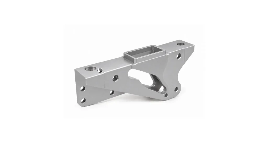
Worked example: 7075-T6 aerospace bracket
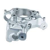
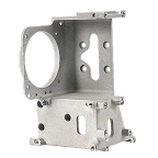
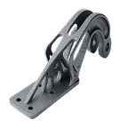
Consider the 7075-T6 Aluminum bracket above with:
- 0.8 mm thin walls
- ±0.025 mm profile tolerance
- Ra 1.6 µm surface requirement
- deep pockets
- several critical bores
Proposed process
Roughing
- adaptive toolpath
- climb milling
- low radial engagement
- substantial axial engagement
- controlled cutter engagement angle
Semi-finishing
- climb milling
- controlled remaining stock
- inspect for wall movement
Thin-wall finishing
Trial two strategies:
Strategy A: climb finish
Strategy B: conventional finish
Measure wall thickness, profile, taper, Ra, chatter and tool marks.
Suppose Strategy A gives:
- wall thickness: 0.84–0.87 mm
- profile error: 0.041 mm
- Ra: 0.9 µm
Strategy B gives:
- wall thickness: 0.80–0.82 mm
- profile error: 0.018 mm
- Ra: 1.2 µm
Both satisfy the surface requirement, but Strategy B provides considerably more margin against the profile tolerance.
For this feature, on this machine, fixture and tool combination, conventional finishing is the better production process. That conclusion applies to the demonstrated operation rather than to conventional milling in general.
Troubleshooting by symptom
| Symptom | Check First | Relevance of Cutting Direction |
|---|---|---|
| Poor surface finish | Built-up edge, runout, chip recutting, cutter wear, feed and vibration | Change direction after eliminating more direct causes |
| Thin-wall taper | Stick-out, finishing allowance, wall support, holder rigidity and deflection | Trial both directions if force direction is affecting profile |
| Rapid tool wear | Cutting speed, chip load, engagement, heat, coolant and material condition | Important where rubbing or work hardening is evident |
| Chatter | Spindle speed, tool stick-out, fixture stiffness, engagement and tool geometry | Direction may matter if the changed force vector alters stability |
| Burrs | Exit condition, cutter sharpness and material ductility | Direction can change the edge at which the cutter exits |
The defect itself should determine the investigation rather than an assumption that either climb or conventional milling is responsible.
Practical decision table
| Condition | Starting Strategy | Engineering Reason |
|---|---|---|
| Rigid modern CNC, normal peripheral milling | Climb | Good chip formation and generally favorable cutting conditions |
| Older machine with significant backlash | Conventional | Reduces risk of cutter pulling the feed system through its clearance |
| Low radial engagement | Usually climb | Efficient peripheral cutting and controlled chip formation |
| Full-width slot | Evaluate adaptive/trochoidal strategy | Engagement, heat and evacuation can dominate |
| Thin-wall finish | Trial both | Deflection direction can determine accuracy |
| Work-hardening alloy | Maintain positive chip formation | Reduces rubbing against affected material |
| Abrasive cast/forged skin | Application dependent | Cutter entry and edge loading dominate |
| Poorly supported part | Evaluate force vector | Workholding may determine the preferred direction |
| Surface-finish-critical pass | Usually climb, verify | Often gives a good finish under stable conditions |
| Deflection-limited finish | Conventional may help | Cutter deflection can act more favorably relative to the finished surface |
Use the table as a starting point, then confirm the strategy by machining trials and inspection.
Supplier approval
Pre-meeting supplier check: Before arranging a visit, review the supplier’s machine capability, backlash control, spindle power and rigidity, available tooling, workholding approach and experience with climb milling in the specified material.
Ask how they control feeds, speeds, radial and axial engagement, tool life, chip evacuation and CNC program revisions.
Request representative inspection records, surface-finish results and, where relevant, capability data for comparable parts.
Supplier visit validation: At the supplier, verify the proposed machine, fixture, cutter and toolholder against the documented process. Observe the cutting direction, entry and exit, chip evacuation and any deflection of thin or flexible features.
Review first-piece inspection, tool-life controls, program and offset management, calibrated inspection equipment and traceability.
Confirm that critical dimensions and surface finish can be reproduced consistently and that required FAI, PPAP or other production records are controlled.
Treat the supplier-approval checklist as work an accountable manufacturing arm does on your behalf: verify machine capability and lock the proven process, then own the outcome on time and on spec. You decide based on the measured part. The job of a supplier of record is to keep cut direction a controlled, audited parameter, so it never silently drifts between the first article and the production lot.
The practical takeaway
Climb milling remains the sensible starting strategy for a large proportion of modern CNC machining. Rigid machines, low backlash and controlled CAM toolpaths make it efficient and predictable.
Conventional milling still has legitimate uses, particularly on backlash-prone equipment and where thin-wall deflection, difficult surface conditions or the direction of cutting force affects the finished geometry.
For production work, the choice should be based on the measured component. Establish the cutting conditions on the intended machine and fixture, inspect the characteristics that matter, and retain the process that gives sufficient margin against the drawing requirements.
Frequently Asked Questions
What is the difference between climb milling and conventional milling?
In climb milling, cutter rotation and feed act in the same direction at the cutting interface and chip thickness progresses from thick to thin. In conventional milling, cutter rotation opposes feed and the chip progresses from thin to thick. These differences influence cutting force, rubbing, heat, tool wear and surface finish.
When should you use conventional milling instead of climb milling?
Conventional milling can remain useful on machines with significant backlash and when entering hard or abrasive surface layers such as casting skin, forging scale, hot-rolled scale or some torch-cut surfaces. It can also be useful in particular thin-wall, high-engagement or specialized tooling situations.
Does climb or conventional milling give a better surface finish?
Climb milling generally gives the better finish on a rigid, stable setup, but it is not universal. Tool and workpiece deflection, runout, built-up edge, chip evacuation, tool condition and engagement can override the theoretical advantage.
The brief specifically identifies a deflection-limited exception in which conventional milling can produce a better finishing result.
Why does climb milling require low backlash?
Climb cutting forces can pull the work/table in the feed direction. Mechanical free play can therefore cause the cutter to take a much larger instantaneous chip than programmed.
The brief’s worked example combines a 0.005 in. programmed chip load with 0.020 in. backlash to illustrate a possible 0.025 in. effective entry movement, enough to seriously overload a small cutter.
Should climb milling be specified on an engineering drawing?
Usually the drawing should specify the required finished result, including dimensions, GD&T and surface texture. Cutting direction is often better controlled in the approved process plan and CNC/CAM program.
Where a particular machining strategy is itself necessary to achieve a functional or contractual requirement, it can be explicitly controlled. The brief similarly distinguishes between calling out milling strategy and leaving it to a validated process.
Does climb milling always increase tool life?
No. Climb milling often creates favorable chip formation and can reduce rubbing and heat, but tool life also depends on material, cutter geometry, cutting speed, chip load, engagement, toolholder stiffness, coolant, chip evacuation and machine condition. The brief specifically cautions against presenting claims such as “50% longer tool life” as universal benchmarks.