
A counterbore can seem specified on a drawing, but still produce an assembly problem.
The diameter may provide clearance, but the screw head sits proud. The recess may be deep enough, but the counterbore may be eccentric from the clearance hole. Paint may reduce available clearance. A burr or cutter radius may prevent the underside of the fastener head from reaching the intended seating surface.
These are small geometric differences, but they can result in rejected first articles, rework, assembly problems, or scrap.
The valuable decision driver is therefore ‘what does the fastener need, and how should that requirement be translated into dimensions, tolerances, manufacturing controls, and inspection criteria?’
That approach is the key to specifying counterbores that suppliers can manufacture consistently and inspectors can verify reliably.
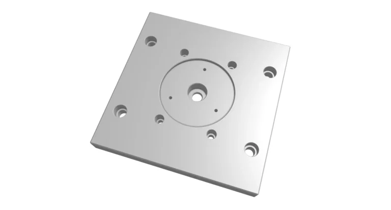
What a counterbore actually does
As described, a counterbore is a cylindrical and flat bottomed recess, cut coaxially with a hole. It normally provides clearance for a fastener head, while creating a flat seating surface.
The feature is commonly required for socket head cap screws, but counterbores can also accommodate other cylindrical or hexagonal heads, washers, locating hardware, plugs, and similar components.
Three superficially similar features need to be distinguished:
| Feature | Geometry | Primary Purpose |
|---|---|---|
| Counterbore | Cylindrical recess with a substantially flat bottom | Recess a fastener head or component |
| Countersink | Conical recess | Seat a matching conical fastener head |
| Spotface | Localized shallow machined bearing surface | Provide a clean, flat seating surface |
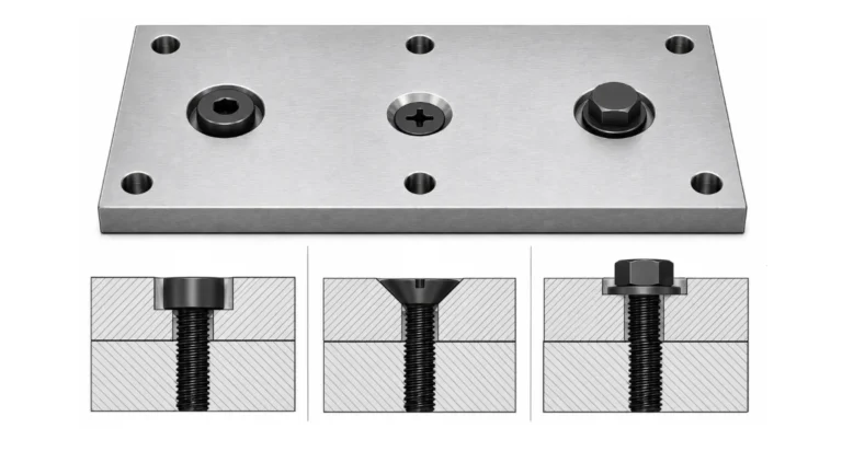
The distinction between a counterbore and spotface is primarily functional, rather than being defined by an arbitrary depth.
A spotface is typically used where the surrounding surface cannot provide a flat or smooth contact face, such as a casting, forging, curved component, or rough-machined face. A counterbore normally provides sufficient depth to recess all or part of the fastener head.
A countersink screw requires a matching feature as a recess to accommodate the head. A socket head cap screw that must sit below the surface, or flush with it, will require a counterbore.
The fastener and assembly requirement drives the feature selection.
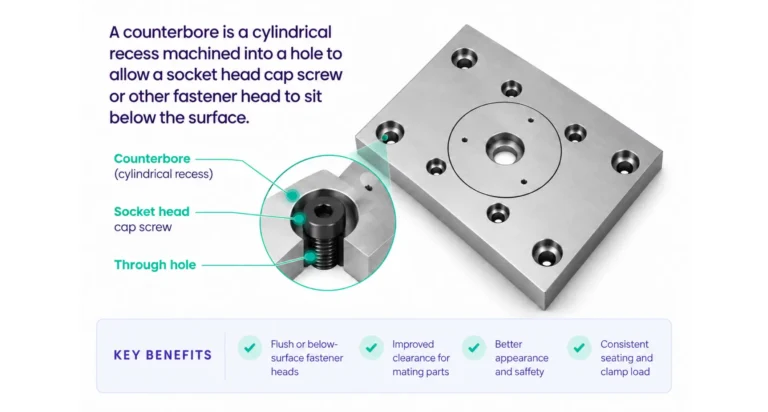
Start with the fastener, not the counterbore
One of the easiest drawing mistakes is to choose a convenient counterbore diameter and depth first.
In reality, the counterbore must be defined to suit the selected fastener.
The engineer needs to establish the relevant fastener head dimensions, particularly maximum head diameter and maximum head height, from the applicable standard or manufacturer’s controlled data.
For inch socket head cap screws, relevant standards include ASME B18.3 and the applicable clearance-hole standard. Metric socket head cap screws reference ISO 4762/DIN 912 together, with ISO 273 clearance-hole recommendations.
The applicable standard current edition should always be checked, before putting fixed values onto a CAD model or production drawing.
Different fastener forms also require different treatment. A standard socket head cap screw, low-head socket screw, button-head screw, and hex-head fastener do not have interchangeable head envelopes.
The counterbore therefore should not be designed around a generic nominal screw size alone.
The functional tolerance stack
A counterbore is best treated as a restricted tolerance-stack problem.
The minimum counterbore diameter must exceed the maximum fastener head diameter, by a required radial/diametral assembly clearance
The required clearance depends on the application.
A fastener installed manually in a non-critical cover may tolerate generous clearance. An automated assembly operation, close-packed bolt pattern, precision fixture, or component with tight surrounding geometry may require more selective/restrictive control.
The minimum acceptable counterbore depth must be greater than (at least equal to) the maximum fastener head height, plus the required recess allowance
If a head must sit 0.25 mm below the surrounding surface, that requirement belongs in the stack. Simply making the nominal counterbore depth equal to the nominal head height does not guarantee a recessed condition.
The engineer must specify the recess to accommodate:
- maximum head diameter
- maximum head height
- counterbore diameter tolerance
- counterbore depth tolerance
- required assembly clearance
- required head recess
- surface finishing or coating buildup
- burr and edge conditions
- cutter corner geometry (internal corner recess radius)
- variation in the surrounding machined surface
This is more reliable than applying a universal rule such as “make the counterbore 0.010 in larger” or “machine it 0.020 in deeper.”
Rules of thumb can be useful during preliminary design, but production dimensions should come from the actual functional stack.
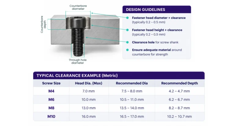
Counterbore diameter: Specify clearance and tolerance as two separate numbers
Counterbore clearance and counterbore manufacturing tolerance are different metrics.
Suppose a designer determines that a particular fastener head needs a counterbore of a minimum functional diameter. The designer must then choose a nominal dimension and tolerance that guarantee that minimum, without undue machining cost or weakening the surrounding geometry.
A specification such as:
ØD ± t
does two separate jobs.
D – establishes the intended size (diameter).
t – determines how much manufacturing variation is permitted.
If the fastener can be provided ample clearance and the surrounding material permits it, a relaxed diameter tolerance may perform well.
Tighter tolerances typically require a functional reason. This is particularly important when several counterbores are placed close together or near an edge. An unnecessarily large counterbore may reduce wall thickness, creating consequent risks, even though the fastener itself fits comfortably.
Counterbore depth: Define the required result
Depth is one of the most common sources of counterbore application issues.
If a drawing specifies a counterbore at exactly the nominal fastener head height, normal variation in the fastener, machined surface, counterbore depth, burr condition, or cutter geometry can leave the head above the surrounding surface.
Instead, define the required assembled condition.
If the screw must be below flush, the tolerance stack should guarantee below-flush seating at worst case.
Conversely, simply adding excessive depth is not good engineering. Deeper counterbores increase machining time and can reduce the remaining floor thickness.
The drawing should provide enough depth to meet the functional requirement while preserving adequate material.
Watch the remaining floor thickness
A deep counterbore in a thin component can leave very little material between the counterbore floor and the opposite face.
That remaining section may distort under fastener preload, crack, deform during machining, or become vulnerable to breakthrough.
There is no useful universal minimum floor thickness.
The appropriate value depends on factors including:
- material
- counterbore diameter
- fastener preload
- support around the joint
- component geometry
- loading
- whether the clearance hole passes completely through the remaining material
Ascertain if the standard minimum floor thickness need is met. Can the remaining material safely carry the expected clamp and service loads?
Where the answer is uncertain, the section should be checked structurally, rather than relying on a generic machining rule.
Position and orientation matter too
Diameter and depth alone do not always completely define counterbore function.
Consider a counterbore with plenty of diameter clearance but whose axis is offset from the clearance hole. The screw may enter the hole but contact one side of the counterbore.
Likewise, a seating surface that is significantly out of square with the fastener axis can produce uneven loading.
The drawing should therefore control the relationships that matter to the assembly, adding a concentricity tolerance only of it adds value.
In many designs, position provides a more useful way of controlling the relationship between the hole pattern, counterbore and relevant datum structure.
Ask what feature locates the fastener?
Usually it is the clearance hole, threaded hole, mating component, or hole pattern. The counterbore normally exists to provide clearance and a bearing surface around that functional axis.
The GD&T scheme should reflect that hierarchy rather than treating the counterbore diameter as the primary locating feature.
For critical applications, the drawing may also need to control the orientation of the seating surface relative to the hole axis or datum structure.
Specify the edge and bottom condition
“Flat bottom” should not be interpreted as mathematically perfect geometry.
Real counterbores are produced by cutters with finite-radius corner geometry. Depending on the process, the bottom-to-wall transition may contain a small radius or chamfer.
That matters if the underside of the fastener head has its own radius or chamfer.
An interference at this corner can prevent the head from reaching the intended seating surface, even though diameter and depth measurements appear acceptable.
Designers should therefore consider:
- allowable bottom corner radius
- fastener underside geometry
- entrance chamfer
- edge break
- burr limits
- whether deburring changes the effective seating condition
Avoid specifying a perfectly sharp internal corner unless the function genuinely requires it, which typically it should not.
Counterbore callouts on the drawing
A counterbore is only as good as the callout that defines it. Under ASME Y14.5, the counterbore is specified with a symbol set the machinist reads directly off the feature control: ⌴ for the counterbore, ⌵ for a countersink, and ↧ for depth. Name the standard on the drawing so there is no question which convention the shop is inspecting to.
The callout reads in a fixed order: the clearance hole diameter first, then the counterbore diameter, then the counterbore depth. Written out, a typical fastener pocket looks like this:
Ø10 ⌴ Ø15 ↧ 5
That string specifies a 10 mm clearance hole, a 15 mm counterbore diameter, and 5 mm of counterbore depth. A machinist reading it knows the through-hole passes the fastener shank, the ⌴ pocket clears the head, and the ↧ value sets how deep the head sits below the surface. Get the order wrong and you invite a diameter swapped for a depth, which is exactly the kind of revision mismatch that surfaces at first-article inspection instead of on the print.
A few things the symbols alone will not carry, so put them on the drawing:
- Show the counterbore in a section view. The pocket geometry and the seat face are hard to read from a top view, and the section removes the guesswork.
- State which side is counterbored. On a symmetric part the callout is ambiguous without a face reference, and the shop should not have to guess.
- Say whether the counterbore is cut before or after finishing. Plating and coating change the effective diameter and the seat, so the sequence belongs on the print, not in a phone call.
- Tie the hole pattern to a datum. A datum-controlled pattern locates every counterbore to the same reference the fastener pattern uses, so position error is measured against the mating condition rather than a nearby edge.
Do not automatically specify surface finish
The bottom of a counterbore is a bearing surface, but that does not mean every counterbore needs a tightly specified Ra condition.
Basic machine finish may provide an entirely adequate seating surface, for most fastened landings.
A specific surface-finish requirement becomes more defensible where bearing behavior, sealing, high preload, fatigue performance, precision location, or another functional requirement makes the condition important.
Adding an arbitrary Ra value to every counterbore will increase manufacturing and inspection cost, without improving the assembly performance.
Specify finish when the function requires it.
How counterbores are manufactured
Counterbores can be produced using several methods.
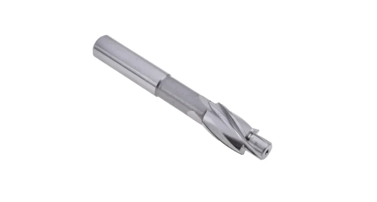
Dedicated or piloted counterbore cutters
A piloted cutter uses the existing hole to guide the counterbore tool. This can provide a direct concentricity relationship between the pilot hole and recess.
It is particularly useful for conventional machining and repetitive features.
Endmills
On CNC equipment, an endmill can produce a counterbore by plunging, circular interpolation, or a hybrid toolpath.
This provides operational flexibility and reduces the need for dedicated tooling, particularly where multiple counterbore sizes are required.
Tool deflection, runout, interpolation accuracy and bottom finish must still be considered.
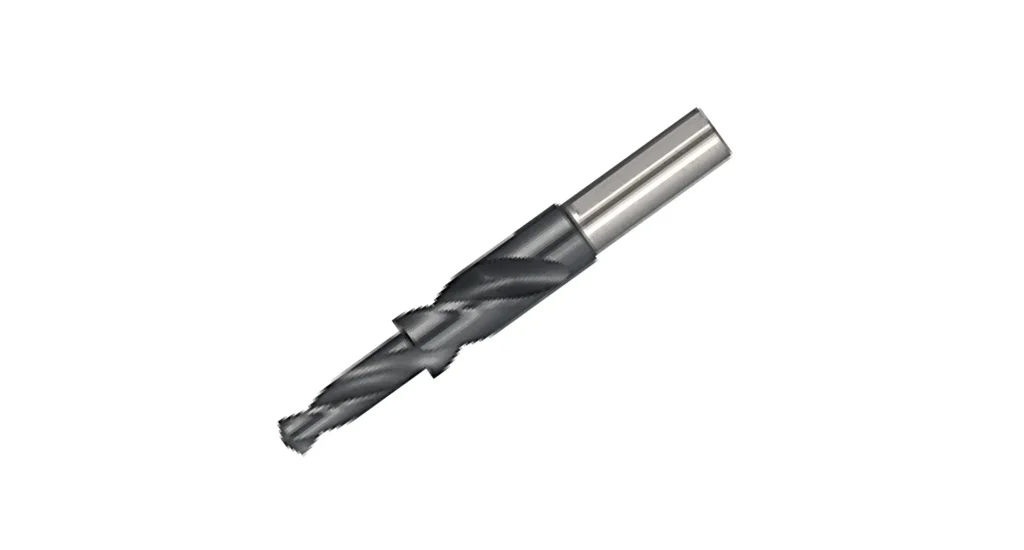
Combination tooling
For higher-volume production, combination drill/counterbore tools can produce multiple feature elements in one operation, reducing tool changes and cycle time.
Back counterboring
Features that must be machined on the inaccessible side of a component may require back-counterboring tooling or a more challenging setup.
Irregular surfaces
Counterbores entering curved, angled, forged or cast surfaces require added caution to tool entry, workholding and the intended reference surface, due to offset loading and potential snagging.
These conditions can make a simple-looking counterbore substantially more difficult to manufacture precisely and with low risk of tool breakage.
Material changes the process
A counterbore that is easy to produce in Aluminum may behave differently in stainless steel, Titanium, or engineering polymers.
Aluminum generally permits high material-removal rates, but can produce burrs that interfere with seating.
Stainless steels can increase cutting forces and create work-hardening or burr-control issues.
Titanium places greater demands on heat management, tool condition and machining strategy.
Plastics may produce different problems, including burrs, deformation, dimensional recovery and sensitivity to clamp pressure.
The drawing should define the functional result. The supplier should then be enabled to select an appropriate manufacturing method, unless the process itself is design-controlled.
Account for Finishing
Counterbores that will subsequently be anodized, plated, painted, or coated require another tolerance-stack decision.
The important question is not simply whether the finish adds thickness. Various finishing processes affect dimensions differently.
The engineer should establish:
- whether the drawing dimensions apply before or after finishing
- whether the counterbore is masked
- whether coating buildup materially reduces clearance
- whether the seating surface itself should be coated
- whether the inspection requirement applies to the finished part
For tight-fitting features, leaving this unspecified can result in parts that pass machining inspection but fail assembly after finish processing.
Blind and through counterbores are different production problems
A through pilot hole generally provides a better path for chip evacuation than a blind feature.
Blind configurations can trap chips at the counterbore floor, particularly when geometry limits coolant access or evacuation.
A trapped chip can make a correctly machined counterbore behave like an undersized or shallow feature during assembly.
For blind features, the designer and manufacturer should consider chip evacuation, bottom geometry, cleaning and inspection access.
How to inspect a counterbore
Inspection should follow the functional requirements established on the drawing.
Diameter
Depending on size and tolerance, diameter can be checked using appropriate bore-measurement equipment or a CMM.
Depth
A depth micrometer or depth gauge can measure the recess relative to the surrounding reference surface.
The measurement method needs an adequate reference area. Very small, curved or interrupted surfaces can make apparently simple depth measurements less reliable.
Location
Where counterbore alignment is functionally important, a CMM or appropriate fixture can verify its runout from the clearance hole and error in the datum structure relationships.
Seating surface
Visual inspection may identify chatter, burrs, embedded chips or damage. Where surface finish is explicitly controlled, an appropriate surface measurement method may be required, though this can pose significant challenges.
Functional inspection
Not every counterbore requires a CMM. In reality, very few might.
For production quantities, a dedicated functional go-no-go gauges or controlled fastener/head seating check may provide a faster and more directly informative test.
The inspection method should answer the same question as the drawing: will the specified fastener assemble and seat correctly?
First article and production control
A counterbore that is important to assembly should not disappear into a generic inspection note.
During first-article inspection, the relevant drawing characteristics should be ballooned and FAI reported individually.
Depending on function, these can include:
- counterbore diameter
- depth
- position
- pilot-hole diameter
- remaining material thickness
- seating-surface condition
- edge condition
- post-finish dimensions
Not every characteristic needs the same ongoing inspection frequency, however.
Critical characteristics may justify statistical monitoring or defined sampling. Stable, non-critical dimensions may require less intensive control.
For programs using FAI, PPAP or a formal control plan, inspection frequency should reflect actual assembly and quality risk, rather than simply measuring every counterbore characteristic equally.
Common counterbore failure modes
Several problems recur in production.
Head sits proud: Counterbore depth does not accommodate the maximum head height, required recess and manufacturing variation.
Head contacts the counterbore wall: Counterbore diameter is too small, finishing has reduced clearance, or the recess is offset from the pilot hole.
Fastener does not seat flat: Burrs, chips, chatter, an excessive bottom corner radius or poor seating-surface orientation prevent full contact.
Counterbore is visibly off-center: Pilot-hole location, tool runout, setup error or an inadequate machining strategy has displaced the feature.
Thin floor distorts under load: Excessive depth leaves insufficient material to support fastener preload.
Assembly works before finishing but fails afterward: Coating buildup was omitted from the dimensional stack.
Inspection results disagree: The drawing does not establish a clear datum, reference surface, edge condition or measurement requirement.
These are rarely “counterbore problems” in isolation. They are specification, manufacturing and verification problems interacting with one another.
A better way to specify a counterbore
Consider a socket head cap screw that must finish below the surrounding surface.
Instead of starting with a remembered counterbore table, work through the requirement systematically.
- Identify the exact fastener details
- Select the pilot-hole clearance
- Establish minimum counterbore diameter
- Establish minimum depth and flush condition
- Select manufacturing tolerances
- Check surrounding geometry
- Consider finishing
- Control location where necessary
- Define edge and seating conditions
- Choose an inspection method
This method manages the counterbore as an engineered feature, rather than a copied handbook dimension.
Specifying counterbores for a clean supplier quote
A supplier can manufacture a counterbore only as clearly as the design defines it.
Before releasing an RFQ, ensure that the drawing and supporting data establish:
- fastener-related dimensions
- counterbore measurements and tolerances
- required edge condition
- relevant surface-finish requirements
- coating or finishing condition
This also improves quotation quality and reduces the need for clarification comms.
If one supplier assumes loose commercial tolerances while another assumes tight inspection requirements, their prices are not based on the same manufacturing challenge.
Clear specifications reduce ambiguity.
For production programs, revision control, first-article inspection, supplier qualification and traceable inspection records become increasingly important. It is not simply about finding a shop that can machine a counterbore, but establishing a repeatable route for receiving the same acceptable feature over long production runs.
Counterbores are a sourcing problem, not just a machining one
A counterbore drawn correctly still fails on the floor. The bore comes in shallow, so the socket head sits proud and won’t pull flat. You catch it at incoming inspection or, worse, at assembly.
That’s a sourcing problem as much as a machining one. Specifying the callout, its depth, the fit class, and the bottom-surface finish is your job. Confirming the shop hit them run after run is where supplier relationships usually go quiet.
Jiga is your custom manufacturing arm for exactly that gap. You talk directly to the shop cutting your parts. A question about counterbore depth or bottom finish reaches the machinist, instead of a black-box quoting desk.
When a date drifts or a supplier goes silent, someone on your Jiga team owns it and resolves it before it reaches your build.
Accountability continues into the paperwork. Jiga is your supplier of record, so first article inspection, certificates of conformance, material certs, and lot traceability come with the parts. PPAP is in place on production programs.
The result is one point of accountability for counterbored parts that arrive on time and on spec, from prototype through full-rate production.
The main principle
A counterbore is simple geometry, but a reliable counterbore specification requires more consideration and data than simply diameter and depth.
Start with the fastener and the assembled condition. Establish the required clearance and recess. Apply tolerances that preserve those conditions in the worst case. Check remaining material, cutter geometry, datum relationships and finishing. Then make sure the inspection method can verify what the drawing actually requires.
That sequence connects design intent to manufacturing and manufacturing to quality control.
And that is ultimately what prevents a feature that looked perfectly acceptable in CAD from returning from production with a screw head sitting proud.
Frequently Asked Questions
What is the difference between a counterbore and a countersink?
A counterbore is a cylindrical recess that normally provides a flat seating surface for a cylindrical or similar fastener head. A countersink is conical and normally accommodates a fastener with a matching conical underside, such as a flat-head screw.
What is the difference between a counterbore and a spotface?
Both can have similar cylindrical geometry, but their functions differ. A counterbore primarily creates space to recess a fastener head or component. A spotface creates a localized flat bearing surface, commonly on an otherwise rough, curved, cast or forged surface.
How do you call out a counterbore on a drawing?
Per ASME Y14.5, call it out with the counterbore symbol ⌴ and depth symbol ↧ in the order hole diameter, counterbore diameter, counterbore depth, for example Ø10 ⌴ Ø15 ↧ 5 (a 10 mm clearance hole with a 15 mm counterbore 5 mm deep). Cite the edition you are working to, since the symbol conventions have changed between releases.
How deep should a counterbore be for a socket head cap screw?
There is no one-depth-fits-all. Start with the maximum permitted fastener head height, add any required below-flush clearance, then select the counterbore nominal depth and tolerance so the required minimum depth is maintained at worst case. Check that adequate material remains beneath the recess.
How should a counterbore diameter be selected?
Start with the maximum fastener head diameter and add the clearance required for assembly. Then establish a nominal counterbore diameter and manufacturing tolerance that guarantee that minimum clearance without unnecessarily removing material or imposing excessive precision.
How do you measure a counterbore?
Diameter can be measured with suitable bore-measurement equipment or a CMM. Depth can normally be checked using a depth micrometer or depth gauge. A CMM can verify location and orientation where these are controlled. For production, a functional gauge may sometimes provide a faster and more meaningful acceptance test.