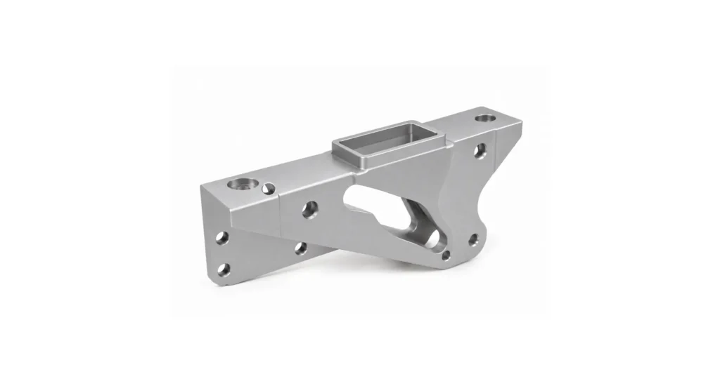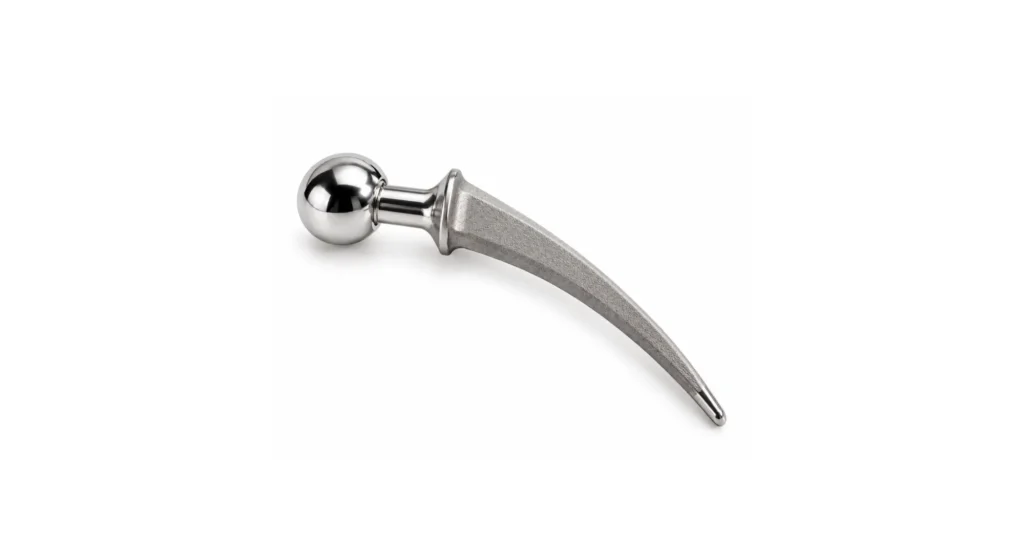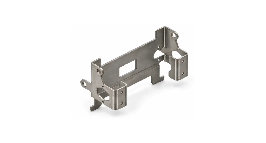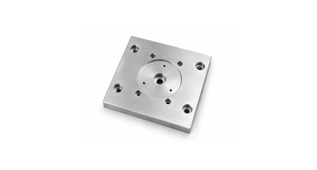
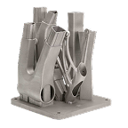
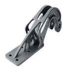
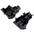
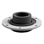

A burr is an unintended projection, ridge, lip, or shard of material remaining attached to a workpiece. Most often this lies at or near an edge, after a cutting or forming operation. In some cases it can be projected directly from a face, due to crossover issues. It typically results from plastic deformation induced material displacement, or incomplete separation during cutting.
A drawing note that simply says DEBURR or BREAK ALL SHARP EDGES sounds clear, until a production lot reaches incoming goods inspection and QA has to decide whether the parts actually comply.
- How much material can the supplier remove?
- Is a small remaining burr acceptable?
- Does “break edge” mean a radius, a chamfer, or simply removal of anything sharp enough to cause a handling hazard?
- How should an inspector verify an internal cross-hole that cannot be touched or seen directly?
These are specification issues, long before they are deburring or inspection problems.
An effective production sequence is to review function, edge requirements that arise from it, and drawing callouts – and then select approaches to burr prevention and removal. Finally, an inspection process must be applied, using realistic acceptance criteria.
If an edge condition is functionally or aesthetically important, define what results are acceptable in advance. Select a manufacturing process capable of producing it, and establish how compliance with these defined acceptance criteria can be reliably verified.

What is a burr, and why is a “sharp edge” not a specification?
A burr is unwanted, uncontrolled and generally ragged looking material, extending from the intersection of two surfaces, or sometimes directly from a surface. Burrs form during machining, drilling, milling, punching, laser cutting, sawing, grinding, and other material-removal processes.
A burr should not be confused with three intentional edge conditions:
- Edge break: controlled removal of the nominally sharp edge without necessarily defining a specific geometry.
- Chamfer: a well defined and consistent flat, usually specified by size and angle.
- Radius: a piecewise-continuous curved transition between surfaces.
These distinctions matter. A requirement note on a drawing such as:
BREAK EDGES 0.005” MAX does not demand the same as 0.005” × 45° CHAMFER
The first controls the maximum permissible departure from the theoretical edge. The second creates a defined geometric feature.
Likewise,notes such as BURR FREE and BREAK EDGE 0.005” MAX are not equivalent requirements. The former prohibits unwanted protruding material. The latter permits deliberate, limited material removal.
This distinction should be established before selecting a deburring process.
Begin with what the edge does
The appropriate edge condition depends heavily on its intended function.
- A nonfunctional, external edge may need generic smoothing, primarily to prevent handling injuries or co-marking issues during assembly.
- A sealing edge may require a controlled radius or chamfer so it can pass by/through an O-ring without cutting it.
- A fatigue-loaded edge may need controlled blending to reduce fracture inducing stress concentrations.
- An internal fluid passage may need strict burr control because detached material could contaminate the system, or the burr could become a preferential deposition zone.
This is why applying one, general deburring requirement to every edge can be unnecessarily expensive, technically inadequate, or both according to region on a part.
A precise radius on every exposed edge adds significant cost, where a simple knock-down may have been sufficient. Equally, leaving a critical sealing or fatigue-risk edge under a vague general note gives the supplier freedom to interpret the requirement and deliver a failed outcome.
The engineering objective is to specify requirements for outcomes only as tightly as function requires, but sufficiently tightly that acceptable function is unambiguously evident.

How to specify deburring on an engineering drawing
An appropriate and thorough edge requirement answers two questions:
- How much excess material is permitted?
- How much material may be removed from the theoretically perfect edge?
There are different conventions for answering those questions.
ISO 13715 edge callouts
The ISO 13715:2017 standard defines a drawing convention for edges of undefined shape.
This distinction is important: the standard is useful when the designer needs to control departure from the theoretically sharp edge without defining that departure as a particular chamfer or radius.
The notation distinguishes between material extending beyond the theoretical edge and material removed from it.
In simplified terms the notation addresses permitted excess material, such as a burr. Then it addresses permitted removal of material, such as an edge break.
The numerical requirement controls the permitted deviation region, rather than defining a chamfer angle or radius.
If the functional requirement actually needs a specific 0.25 mm x 45° chamfer, specify that geometry. If the requirement is simply to control how much the real edge may depart from its theoretically sharp location, ISO 13715 provides the appropriate language.
The current edition is ISO 13715:2017, which replaced the 2000 edition.
ASME Y14.5 and edge-break notes
ASME Y14.5 does not provide an equivalent dedicated GD&T “break edge” symbol. On ASME-governed drawings, edge requirements are therefore commonly communicated through notes, or explicitly dimensioned geometry.
Examples include the note REMOVE BURRS AND SHARP EDGES
or, preferably where control matters it should read BREAK SHARP EDGES 0.005” MAX
The second requirement is easier to inspect, as it establishes a dimensional boundary that can be tested.
A drawing should also avoid casually mixing standards conventions. If ISO 13715 notation is used on a drawing otherwise governed by ASME practices, its applicability should be clearly identified, rather than assuming every supplier and inspector will interpret the symbol similarly.
The objective is not choosing ISO over ASME for engineer preference. It is ensuring that the supplier and receiving inspector are working from the same definition of what is acceptable.
How much edge break should you specify?
There is no universally applicable edge-break value.
Values ranging from 0.003” to 0.015” maximum appear in production practices. Selecting from this range must be driven by function, geometry, material characteristics, and inspection requirements.
A general handling edge can be specified with considerably more leeway than a precision locating hole, or sealing interface.
| Edge Function | Better Specification Approach | Main Concern |
|---|---|---|
| Handling edge | General maximum edge break | Personnel safety |
| Cosmetic enclosure | General controlled break | Appearance |
| Precision mating feature | Local numeric requirement | Fit and location |
| Seal interface | Defined radius/chamfer | Seal damage |
| Fatigue-critical edge | Engineering-defined treatment | Stress concentration |
| Locating hole | Controlled local edge condition | Position and seating |
| Internal fluid passage | Burr/protrusion limit | Flow and contamination |
| Medical fluid path | Explicit edge/particulate requirement | Debris release |
Shop defaults can be useful for noncritical features, but they should not be allowed to substitute by default for engineering intent.
If a feature matters enough that accepting or rejecting the part depends on it, put the precise requirement on the drawing with simple clarity, long-prior to inspection and rejection risk.
Prevent the burr before choosing how to remove it
Deburring cost is essentially locked-in before the deburring operation begins.
Burr formation depends on material properties, tool geometry, tool wear, cutting parameters, machining direction, workholding, and the sequence in which features are produced.
Material heavily influences characteristic burr behavior, but it should not be thought of as the sole predictor.
Aluminum alloys can produce significant plastically deformed burrs. Austenitic stainless steels can produce persistent burrs while also work-hardening during machining. Titanium can create difficult exit burrs during drilling, and presents highly differentiated cutting and thermal challenges.
The actual result, however, depends heavily on the process, operator choices, and tool/equipment condition.
A steadily increasing burr during a production run can indicate tool wear or machine-settings drift. That makes burr condition useful as a process-control signal, rather than merely a defect to remove downstream.
Good DFM can reduce the problem greatly.
Where geometry permits, engineers and manufacturing teams can:
- orient drilling so exit burrs occur on accessible surfaces
- avoid inaccessible intersecting passages where practical
- machine toward a sacrificial or noncritical surface
- provide tool access to features requiring controlled edge treatment
- sequence machining so later operations do not recreate burrs
- monitor burr growth as part of tool-life management
The least costly burr to handle is the one that the upstream process never creates.

Match the deburring method to the requirement
No single deburring process is optimal for every geometry.
| Method | External Edges | Internal/Cross-Holes | Edge Control | Dimensional Effect | Typical Application |
|---|---|---|---|---|---|
| Manual deburring | Excellent access-dependent capability | Poor | Operator-dependent | Low if controlled | Low volume, accessible features |
| Brushing | Good | Limited | Moderate | Generally low | External machined edges |
| Tumbling/centrifugal | Good | Poor to limited | Moderate | Can round exposed features | Batch production |
| Robotic/on-machine | Excellent where accessible | Limited by tool access | High | Controlled | Repeat production |
| AFM | Good | Excellent | Process-dependent | Material removal must be controlled | Complex internal passages |
| TEM | Good | Excellent | Good for suitable burrs | Requires process qualification | Intersections/internal burrs |
| ECM | Good | Excellent | High | Controlled electrochemical removal | Precision internal features |
| Electropolishing | Good | Geometry-dependent | Broad surface treatment | Removes material globally | Stainless and suitable alloys |
Manual deburring is attractive because it is flexible, but accessibility and operator skill variations limit its use in reality.
Mass finishing, such as abrasive drum deburring, works well for suitable external geometry and volume production, but can alter edges indiscriminately.
For intersecting internal passages, the problem changes completely. A tool, brush, or tumbling media that cannot reliably reach the burr cannot reliably satisfy the requirement. Processes such as abrasive flow machining (AFM), thermal energy method (TEM), or electrochemical machining (ECM) may become appropriate.
Electropolishing can simultaneously smooth edges and improve surface condition on suitable materials, but it removes material from more than just the burr. Dimensional impact therefore must be considered in both machined dimensions and process qualification.
The drawing requirement and the deburring method must be compatible, to ensure the outcome is as required.

Inspection and acceptance are different problems
Inspection asks what edge condition is actually present.
Acceptance asks if that condition is permitted by the drawing.
Those questions are often conflated.
An inspector can use a microscope to measure a burr precisely and still have no objective basis for accepting or rejecting it if the drawing simply says “DEBURR.”
For straightforward external edges, visual inspection combined with a tactile check can provide a practical production-screening method.
More difficult features may require:
- magnification or optical microscopy
- borescopes for internal features
- optical measurement systems
- profilometry
- dimensional inspection where edge removal affects controlled geometry
The inspection method should match the tolerance.
A general safety edge does not necessarily justify micron-level profilometry. Conversely, a critical internal passage should not be accepted simply because an operator cannot feel a burr.
Write acceptance criteria that survive receiving inspection
Consider a drawing note BREAK ALL SHARP EDGES 0.005” MAX
That note offers much more information than “DEBURR” because it creates an inspectable outcome.
For an aerospace first article, the requirement can then flow through the quality system:
- drawing note
- ballooned characteristic
- inspection requirement
- recorded result|
- accept/reject
The key aspect is traceability.
A drawing requirement that never appears in the inspection plan can effectively evaporate between engineering and production.
For AS9102 first article inspection, edge-condition requirements that are included as drawing characteristics must be validated as met, and recorded appropriately in the inspection record. Similar principles apply to PPAP and other production-quality systems: requirements are to be translated into evaluation of controlled characteristics with a consistent and applicable verification method.
This is particularly important when one general drawing note applies across multiple, potentially hundreds of features.
Deburring, cleaning and FOD control
Deburring creates contamination, while deliberately removing extraneous – but attached – material.
Fragments, abrasive media, metallic particles, polishing residue, and other debris can remain on, or even embedded in the component, or become trapped inside internal galleries in a deburred part.
Parts should therefore be sufficiently clean before inspection and deburring to distinguish actual burrs from contamination, then cleaned again after the deburring operation.
Blowing debris around with uncontrolled compressed air may simply move the problem elsewhere. Vacuum extraction and appropriate controlled cleaning methods are preferable, where foreign object debris is a concern, such as in contamination-sensitive components for medical or semiconductor applications.
In aerospace production, this connects edge treatment directly to FOD control. In medical and fluid-handling applications, a detached burr can similarly become a particulate contamination hazard.
Deburring is therefore not finished when the mistaken/extraneous material has been cleanly detached. The resulting debris has to be removed, for process completion.
Common edge-condition failures
Poor edge specification can create failures beyond an unpleasantly sharp component.
- Fatigue initiation: Sharp transitions and machining defects can increase local stress concentration.
- Seal damage: An uncontrolled edge can cut or abrade an elastomer seal during assembly.
- Coating/plating problems: Sharp edges can produce poor coating and plating coverage, while burrs can also create irregular buildup.
- Assembly errors: Burrs around locating or mating surfaces can prevent complete seating, introducing unpredictable alignment errors.
- Internal contamination: Detached burrs can enter and disrupt/damage hydraulic, pneumatic, medical, patient, or process-fluid systems.
- Fixture mislocation: An apparently minor burr, under a datum or locating surface can shift mating components during inspection or assembly.
These are reasons to control specific edges based on function, rather than apply high effort and often costly advanced-deburring requirements indiscriminately.

Suppliers approval for edge and deburr control
When edge condition matters, supplier qualification should examine the supplier’s actual process rather than certification status alone.
Things to investigate:
- How are general drawing edge notes translated into shop-floor instructions?
- How are inaccessible burrs inspected?
- How is increasing burr size used to identify tool wear?
- How is material loss controlled during tumbling, AFM, ECM, or electropolishing?
- Can the supplier demonstrate the required edge condition on the specified material and geometry?
- What happens when the drawing requirement is ambiguous?
The last question is particularly good at exposing gaps in communication strategy.
A capable supplier will flag an uninspectable or contradictory requirement, before production, rather than silently substituting a shop default to ‘solve’ the exposed issue.
For production programs involving multiple suppliers, Jiga is your manufacturing arm and supplier of record, closing drawing, process, inspection, and documentation gaps prior early. The objective is straightforward: one point of accountability which is responsible for parts arriving on time and on spec.

The bottom line
Deburring should not begin with the question, “How should the supplier remove the burr?”
It begins much earlier, with: “What edge condition does this component actually require?”
From there, define an inspectable drawing requirement, design the manufacturing sequence to minimize burr formation, choose a deburring method capable of reaching and controlling the feature, and establish how the resulting edge will be verified.
That turns deburring from an operator judgment at the end of production into a controlled engineering characteristic.
When all the process steps are connected, there is much less room for a supplier’s interpretation of “sharp” and ambiguity at receiving inspection is banished, with a far clearer path to repeatable production.
Frequently Asked Questions
How do I specify deburring or edge break on an engineering drawing?
Define the permitted finished edge condition rather than simply writing “DEBURR.” Use an appropriate ISO 13715 edge requirement, an explicit maximum edge-break note, or a dimensioned chamfer/radius where geometry matters. Critical edges should receive local requirements rather than relying on a general drawing note.
What is an acceptable burr height or edge break for aerospace precision parts?
There is no universal value. Limits such as 0.003, 0.005, 0.010, and 0.015 inch appear in manufacturing practice, but acceptable edge condition depends on function. Sealing, fatigue, locating, fluid-path, and other critical features may require tighter or geometrically defined requirements.
ISO 13715 vs ASME Y14.5: which should I use for edge callouts?
Use the convention appropriate to the drawing’s governing standards and make its interpretation explicit. ISO 13715 provides dedicated notation for edges of undefined shape. ASME Y14.5 drawings commonly control edge condition through notes or explicitly dimensioned geometry. Avoid introducing notation from another convention without defining its applicability.
What is the best deburring method for internal passages and cross-holes?
The geometry largely determines the answer. Manual tools, brushes, and mass-finishing processes may not reliably reach intersecting internal features. AFM, TEM, ECM, and other specialized processes can address internal burrs, but process capability and dimensional effects must be evaluated against the drawing requirement.
How do you verify that a part is properly deburred?
Start with the acceptance requirement. Accessible, non-critical edges may be verified visually and by touch. Internal or tightly controlled features may require borescopes, optical microscopy, profilometry, or dimensional measurement. Inspection only becomes meaningful when the drawing defines what constitutes an acceptable edge.