
Custom sheet metal bending appears simple in CAD. Define a flange, assign a bend radius, generate the flat pattern, and send the file to a press brake.
The finished position of that flange depends on material thickness, specific material properties with wide ranges, grain direction, punch and die geometry, bend method, springback compensation, bend allowance, backgauge position, machine compensation, bend sequence, and the repeatability of the complete forming process.
The starting point is to answer this sequence:
Define the finished geometry, develop a press-brake process that produces it, verify the first parts, and control the variables that keep production in tolerance.
Securing this sequence is the difference between a part that looks bendable in CAD and a production component that arrives on spec, in volume.
To outline this in practice, we will follow one representative component through the process: a 2 mm 5052-H32 aluminum electronics bracket with multiple 90° bends, various mounting holes, critical mating flanges, and moderate precision in finished positional requirements.
What custom sheet metal bending actually means on a press brake
A press brake forms sheet metal by forcing the material between a punch and die set to form bends, to preset radii and angle.
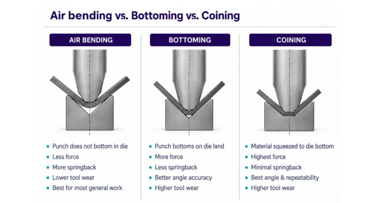
Three common forming approaches are air bending, bottoming, and coining. There is a tradeoff on which approach is used: increasing die contact and forming force can improve angle control, and reduce springback, but at higher load and with less flexibility than air bending.
Air bending
In air bending, the sheet contacts the punch and the shoulders of the V-die, but does not fully conform to the die cavity.
It is widely used because one tool combination can create a wide range of bend angles – reducing tool specificity and overall tooling needs. An added benefit is that the required tonnage in the press is comparatively modest.
The actual inside radius is influenced strongly by the die opening, material and thickness – but not precisely controlled. It cannot be assumed to equal the punch-tip radius – it will range from the tip radius (minimum) and upwards according to material properties, thickness, “V” width, and operational techniques.
Air bending also generally creates the most springback of the three methods, requiring trial and skill in compensation for it.
Bottoming
Bottoming drives the sheet farther into the die “V” and increases contact between the workpiece and tooling.
It can improve angle consistency and reduce the amount of springback that must be compensated for, compared with air bending. This increases force and reduces flexibility (and need for operator skill).
Coining
Coining uses substantially greater pressure, and plastically compresses material at the bend.
It can provide tight angular control, but requires higher press tonnage and is generally reserved for cases where its specific advantages justify the additional tooling cost and machineload.
For most production sheet metal, the choice is driven by providing the required geometry, repeatability, tooling flexibility and production economics.
Follow one bracket through production
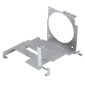
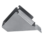
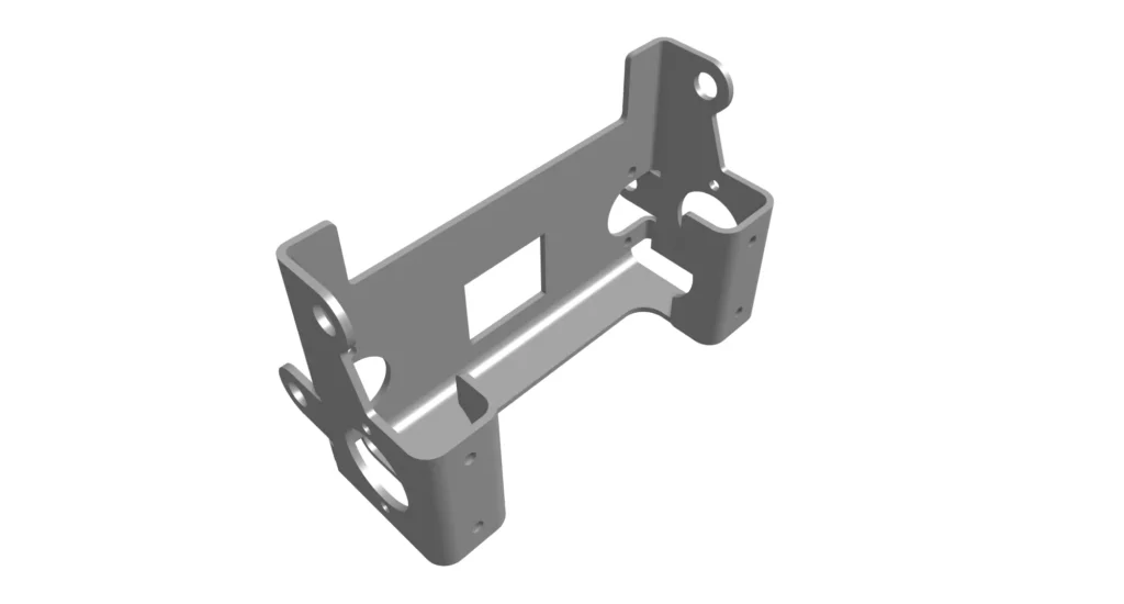
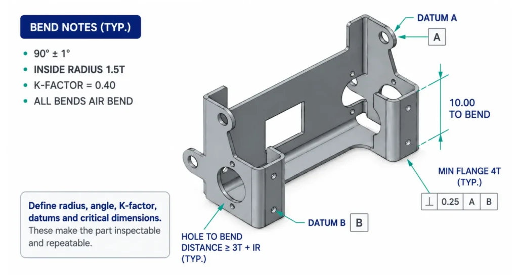
Consider the 5052-H32 Aluminum bracket formed from a 2.0 mm sheet, shown on Fig 1.
The finished part contains:
- a 100 mm base
- multiple nominal 90° flanges
- multiple mounting holes
- holes in the bent flanges
- inside bend radii
- critical positional relationships between flange holes and the base mounting pattern
- powder coating after forming
Each production stage can influence whether the delivered bracket actually fits its mating assembly. Errors will accumulate, as sequenced bends add potential for variations and these pile up through sequential operations.
That is why press-brake operational design cannot stop at the nominal bend angle.
Bend radius, neutral axis and K-factor
When a sheet is bent, material on the outside of the bend stretches, while material on the inner side compresses.
Between them lies the neutral axis, a region whose net-length changes minimally during bending.
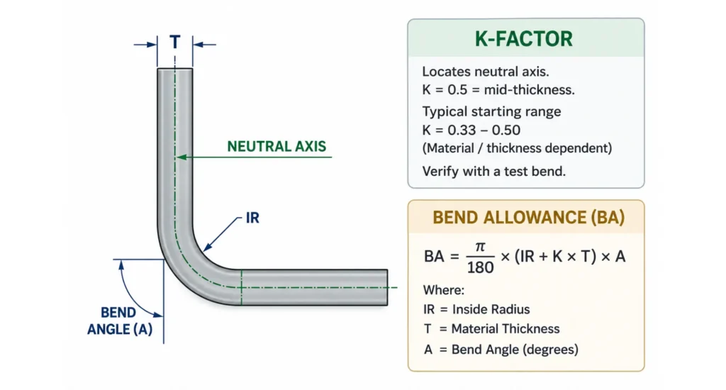
The K-factor represents the position of that neutral axis through the material thickness – the distance from the inner face.
A K-factor of 0.5 would place the neutral axis at mid-thickness. In production bending, values lower than this are commonly used as starting points, approximately 0.33 to 0.50 being a practical initial range.
An assumed K-factor is only an estimate until it is validated against the actual material and tooling combination.
K-factor is a flat-pattern development value, not a fixed material constant.
Bend allowance
A common bend-allowance expression is:
BA = (π / 180) × A × (IR + K × T)
where:
- BA = bend allowance
- A = bend angle in degrees
- IR = inside bend radius
- K = K-factor
- T = material thickness
Bend allowance represents the length of material consumed through the bend region – essentially it defines material lost during bending that must be allowed for, in flat patterning.
Manufacturing process choices may instead work using bend deduction, setback or validated bend tables.
These are essentially variances in representation of the same practical problem, answering the question:
How long must the flat blank be so that the formed part reaches the required finished dimensions?
Do not rely on a generic K-factor for production
For our bracket, CAD might initially generate the flat using:
T = 2.0 mm
IR = 2.0 mm
K = 0.40
A = 90°
This will produce an acceptable first estimate. But the production shop should not assume that the theoretical flat will remain correct across machines, dies and materials.
A strong production workflow is:
- laser cut a trial flat-pattern
- perform the bends manually, using approximate production punch, die and press brake.
- measure the final bend angles and flange dimensions
- estimate the required bend allowances or bend deductions that result
- update the CAD/CAM bend table to compensate for prototype outcome-reality
- repeat the prototype and iterate until the flat pattern and process deliver the formed outcome required
A bend table proven on Supplier A’s tooling should not automatically be assumed to reproduce the same result on Supplier B’s machine and dies. A repeat of the validation sequence is the only reliable way to ensure that settings and choices have been adjusted to compensate for detailed and non-obvious divergence in process steps.
Minimum bend radius is material-specific
Minimum bend radius is very dependent on alloy, temper, thickness, grain direction and forming process.
| Material | Example Minimum Inside Radius |
|---|---|
| Mild steel | Approximately 0.5T |
| 304 stainless | Approximately 1T |
| 5052-H32 | Approximately 1T |
| 6061-T6 across grain | Approximately 2T |
| 6061-T6 along grain | Approximately 3–4T |
These are design starting points, rather than universal and definitive guarantees.
6061-T6 is particularly useful for illustrating why material names alone are not enough.
A bend that is safe across the rolling direction will present substantially increased crack risk, when the bend line is oriented closer to alignment with the grain.
For bend-critical designs, the drawing or manufacturing definition will therefore need to control grain orientation relative to the bend, in highly anisotropic alloys.
Grain direction affects more than cracking
Grain direction often influences springback and consistency.
A supplier who rotates the flat pattern 90° on the sheet purely to improve material utilization risks altering forming behavior in harmful ways.
When grain orientation matters functionally, communicate it clearly.
This directs nesting software, or manual layouts for cutting to optimize the blank for yield, while not disrupting the bend process.
Tooling determines much of what the part becomes
A press brake is only part of the forming system.
For a production part, required tooling information can include:
- punch-tip radius
- punch angle
- V-die opening
- die angle
- tool length
- tooling style
- segmented versus continuous tooling
- tooling condition
Changing any one of these can change the resulting radius, angle, springback, tonnage and cosmetic condition.
V-die opening matters
For air bending, the V-opening width strongly influences the naturally formed inside radius.
As a rule of thumb, the inside bend radius ≈ die opening ÷ 6. This is a starting rule, not a universal geometric law. Actual behavior depends on material and tooling, so real world outcomes must be used to validate/adjust the process.
The central production consideration is that the drawing’s inside radius must be compatible with, and validated from an actual tooling combination and an iterated process.
Check tonnage before releasing the design
A bend can be geometrically valid but physically unsuitable for the available machines.
Required forming force depends on the various factors already discussed.
- a longer bend creates greater total load
- a smaller V-opening generally increases required force
- bottoming and especially coining require greater force than air bending.
For production engineering, tooling selection therefore needs to produce the required geometry, and the machine and tooling must safely carry/deliver the required load.
Long bends also introduce the issue of machine and tooling deflection.
Crowning matters on long bends
A short cutout may form beautifully while a longer edge, such as on an enclosure panel, produces different angles at the center and ends.
This is a direct result of the press-brake ram and bed deflect under load. Better quality machines can compensate using mechanical or hydraulic crowning systems. Planning the method and equipment must take this into account, to deliver a competent and repeatable outcome.
This is the reason first-article data from a small test component cannot prove that a meter-long production bend will behave identically.
The test geometry should represent the actual production condition closely enough to make the calibration meaningful.
Springback is a process result, not a fixed correction
After the forming load is removed, some elastic deformation recovers. This is springback. The final bend angle therefore differs from the angle achieved under maximum load.
2 to 5° of overbend as a typical CNC press-brake compensation range, with greater springback in higher-strength and work-hardening alloys such as stainless steel or Titanium.
Springback varies according to:
- material
- temper
- thickness
- actual yield strength
- bend radius
- grain direction
- die opening
- forming method
- tooling
- process conditions
The required overbend value to achieve a precise final bend angle must therefore be derived from a repeatable bend process performed under otherwise fixed conditions.
Modern CNC press brakes may also use angle measurement and adaptive (real-time) correction, to compensate during forming. This dynamic process better suits low volume parts, as conditions should be stabilized for mass production.
Material thickness variation moves the process
The nominal sheet thickness in CAD is not necessarily the thickness that arrives at the press brake.
A useful ASTM A568 example is nominal 22 gauge material, which may fall over a range of approximately 0.0269 to 0.0329 in.
That variation can affect:
- bend allowance
- formed radius
- tonnage
- springback
- flange position
- flat-pattern accuracy
Material properties also vary between heat-treatment conditions, and even between suppliers of nominally equivalent materials.
For tight production work, locking the CNC program does not control the entire process, if incoming material changes in gross or even subtle ways.
It is for this reason that material lot and certification data are critically important parts of production traceability.
Bend angle tolerance is not flange-position tolerance
This is one of the most important drawing issues in press-brake design.
Suppose our bracket has a 100 mm flange and the drawing specifies 90° ±1°
A tolerance of ±1° sounds tight, at first glance. But the linear displacement at the end of a 100 mm flange caused by a 1° angular change is approximately:
100 x tan 1° ≈ 1.75 mm
That means a flange meeting the angular tolerance can move its end by approximately ±1.75 mm relative to nominal.
If the functional mating of the flange tip must align within ±0.25 mm, the angular tolerance does not adequately control the final outcome.
General bend tolerances, or ISO 2768 alone may not control resultant locations sufficiently.
Control the feature that actually matters
If the real design requirement is the position of a hole on the finished flange relative to mounting datums, tolerance that relationship.
Possible strategies can include:
- position tolerance
- profile tolerance
- finished envelope
- linear dimensions from functional datums
- dedicated checking fixture
The drawing should communicate what the assembly needs, not simply what is convenient for the press brake to measure.
Multi-bend parts create tolerance stack-up
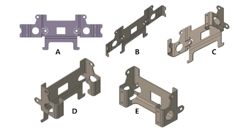
Now add a second bend, as can be seen in the part in Fig 1.
Each bend can contribute:
- angular variation
- bend-line positional variation
- flange-length variation
- material-related springback variation
Two sequential bends can therefore have every bend individually inside its nominal tolerance, while the final envelope is still well out of tolerance.
This makes inspection of the finished geometry more effective than independently checking every bend angle.
For our bracket, the important final requirement might be:
The process needs to be optimized for the finished functional geometry as a net result of the sequence of operations. This is likely to impose closer angular tolerances than may seem appropriate, on first evaluation of the design.
Backgauging controls where the bend occurs
The bend angle tells only half the story. The bend must also happen in the correct location.
The press brake commonly positions the blank against machine elements called backgauge fingers.
Any error in:
- backgauge position
- gauging-edge selection
- blank dimension
- part orientation
- operator loading
- previous bend geometry
can shift the next bend line.
This is particularly important on multi-bend parts because an early error can degrade the reference condition for a subsequent, dependent bends.
The manufacturing plan should therefore identify how the part is gauged, at each stage of operation.
Bend sequence can determine whether the part is manufacturable
A part may contain individually feasible bends, but still be impossible to form in the required sequence.
Imagine a U-shaped channel.
Once the first flange is formed, the geometry available for the second bend changes.
With more complex parts, previously formed flanges can collide with:
- the punch
- die
- ram
- tooling holder
- press-brake structure
Bend sequence therefore belongs in the DFM process, as this can heavily influence design aspects.
The process engineer should determine which bend happens first, which surface is gauged, whether the next bend can be accessed by the tooling – or will an existing flange collide with the machine.
Modern offline press-brake programming can simulate tooling, bend order, backgauge position and collision risk, before the first production blank is formed. This is especially valuable for complex, sequential bend geometries.
Minimum flange length is partly a tooling requirement
Minimum flange length is usually considered to be approximately four times the material thickness, as a starting point.
The underlying reason is not just material behavior. The flange must remain adequately supported on the die during forming.
A flange that is too short relative to the “V” may fall into the die, or become unstable.
The practical minimum therefore depends on material thickness, die opening, and tooling geometry, rather than a single universal multiple of thickness.
Keep holes and slots away from the distortion zone
Material adjacent to a bend experiences significant stretching and compression (on either side of the neutral axis.
A hole placed too close to the bend line can therefore become:
- oval
- stretched
- displaced
- distorted at its edge
A useful starting rule places a feature a distance ≥ 3 x the material thickness PLUS the bend radius away from the nearby wall, for holes and slots near bends.
Example: On 0.125 in. 5052-H32, the distortion zone runs about 0.4 in. from the bend.
Again, geometry and material determine the actual outcome.
A long slot parallel to a bend can behave very differently from a small circular hole.
The most secure design approach is to keep critical features outside the bend deformation zone or provide a validated forming strategy.
Bend reliefs are an important missing piece in many designs
Where two flanges intersect, material can be forced into competing deformation paths.
Without adequate relief, the result can be:
- tearing
- bulging
- uncontrolled overlap
- cracking
- distorted corners
Bend reliefs provide space for the sheet to deform.
The reliefs shape and size depend on thickness, radius and part geometry.
For production CAD, bend relief should be intentionally designed rather than left to whatever automatic relief the software happens to generate.
Laser cutting affects the bend too
The typical workflow includes laser cutting followed by bending, so the upstream blank requires considerable attention, for its influence on process and outcome.
Before bending, check:
- dimensional accuracy of the flat
- burr orientation
- cut-edge quality
- heat-affected edge condition where relevant
- feature position relative to bend lines
- grain orientation
- residual film or contamination
A burr on the wrong side of a severe bend can contribute to cracking or cosmetic defects.
A poorly controlled flat dimension moves the backgauge reference before the bend process even starts.
Bend quality begins upstream of the bending operation itself.
Cosmetic requirements need their own controls
Press-brake tooling contacts the material.
That can leave die witness lines, drag marks, punch tell-tales, and scratches
For internal surfaces and non cosmetic parts, these issues may be irrelevant. For visible medical, consumer or instrumentation components, they may be entirely unacceptable.
Possible production responses include protective film, suitable tooling, urethane protection, controlled orientation, and explicit cosmetic acceptance criteria.
Do not assume that “formed to dimension” also means “cosmetically acceptable.”
Finishing changes what should be inspected
Our example bracket is powder coated after bending. Other parts might be anodized, plated, painted or produced from prefinished sheets.
A finish may add thickness to mating interfaces. In particular, powder-coats may add 2 to 3 mils (roughly 50 to 75 microns). Pretreatment may influence surface condition.
Prepainted or pre-anodized sheets can crack or mark during bending.
Hardware insertion may need to occur before or after coating.
The drawing and process plan should therefore communicate the intended final acceptance state.
Hardware insertion and bending sequence interact
PEM nuts, studs, rivet nuts and other inserted hardware can create another sequencing constraint.
Installing a fastener before bending can:
- obstruct tooling
- affect gauging
- become damaged during forming
Installing it after bending can:
- be impossible due to reduced accessibility
- require a special installation fixture
The manufacturing route should consider bending, hardware insertion and finishing as one sequence rather than unrelated operations.
Welding after bending can move the part again
For fabricated assemblies, forming may not be the final dimensional constraint process.
A part can pass inspection after bending, and move during welding because of thermal distortion and relaxation/recovery of bends as the crystalline structure changes and residual stresses are relieved.
That means final acceptance requirements need to distinguish between formed-part intermediate inspection, and finished-assembly inspection
If welded geometry is critical, measuring every bend perfectly before welding does not guarantee the assembly will conform afterward. This is likely to require constraining jigging to prevent distortion – and potentially some adjustment after welding.
How to specify a bent part on the drawing
A production drawing should focus primarily on the finished function.
Required information can be extensive, fir full control:
- material and thickness
- alloy/temper
- grain direction where required
- finished dimensions
- inside radius where functionally important
- angular requirements
- GD&T
- hole and slot position
- cosmetic requirements
- finishing requirements
- critical datums
- revision
Avoid specifying an arbitrary K-factor as though it were a final product requirement, unless there is a specific reason to control it or it has already been validated by the proposed supplier by prototyping.
Likewise, the designer does not normally need to tell the supplier which size of V-die to use.
| Level | Controls |
|---|---|
| Drawing / model | Finished geometry and functional requirements |
| Flat-pattern definition | BA, BD, bend table, developed blank |
| Process plan | Bend sequence, machine, tooling strategy |
| Press-brake program | Backgauge, ram depth, compensation |
| Setup sheet | Punch, die, tool IDs, orientation |
| Inspection plan | What is measured and how |
| Control plan | Production variables that must remain controlled |
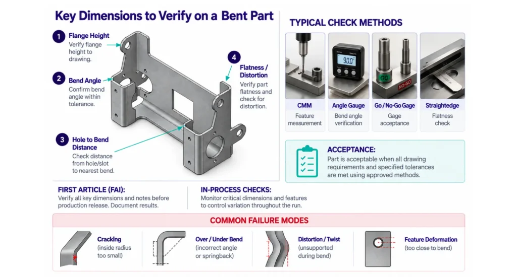
Verify the first article on the finished geometry
After the first bracket is bent, evaluate all factors that actually control assembly and functionality.
For our bracket that might include:
- base length
- flange height
- overall envelope
- hole position relative to datums
- profile of the formed flanges
- bend angles
- inside radius where important
- cosmetic condition
CMM and gauges are relevant precision verification methods, though basic vernier measurements will often suffice.
For production quantities, a dedicated functional checking fixture will certainly be more practical than repeatedly measuring every feature on a CMM.
A good gauge confirms the primary manufacturing issue – will this part fit the assembly and function as required.
First-piece correction should be part of the process
A strong press-brake workflow includes a thorough feedback loop, evaluating the prototype and applying that learning to design and process adjustments to correct errors. It is common to require more than one iteration to finalize design/process details for an acceptable outcome.
The process may need to be repeated for each possible material supply. The press-brake controller may be extremely repeatable, while incoming material properties still change the resulting angles.
Machine repeatability and part outcome are not the same thing.
Control tooling, not just the CNC program
The validated process uses a pre-defined toolset. If a later operation substitutes a similar-looking V-die because the specified one is in use on another machine, the outcome is liable to diverge from acceptance criteria
The CNC program has not changed, but the process has.
The inside radius, force and springback can change in subtle and unexpected ways, due to the substitution.
For repeat production, controlled process information may therefore include EVERY ASPECT of the process and equipment.
Tool condition also matters. Worn tooling can affect radius, angle consistency and surface marking. Monitoring for progressive increases in non-conformance can give early warning of this.
Monitor capability during production
First Article Inspection proves the initial production configuration. It does not prove that the next 5,000 brackets will all behave identically.
For a critical flange, production monitoring can track flange position or finished profile, rather than only bend angle.
For sufficiently important dimensions and production volumes, statistical methods can be used to monitor the distribution, and detect drift early, before parts cross specification limits.
This is particularly useful when separating machine-related drift from material-related variation.
FAI, PPAP and quality-system control
FAI, PPAP, material certification, CoC and traceability are key to any production-quality discussion.
These should, however, be applied according to the actual customer and program requirements.
AS9102 First Article Inspection is commonly used in aerospace, when contract or standards compliance require it. AS9102 uses Forms 1/2/3 with 100% characteristic accountability (AS9100D §8.5.1.3); PPAP can run up to 18 elements; material certs/CoC are retained per §8.5.4.
PPAP may be required in automotive, aerospace APQP environments, or other customer-specific systems.
Neither should be presented as universally required for every press-brake job.
Practical production evidence will include drawings, material certificate/CofC, CNC setup/programs, FAI and process records, and more
It gives supporting evidence that the released design was manufactured under a controlled process, and achieved the required compliance and quality.
Change control matters
A validated bend process can be affected by changes that look minor.
Examples include:
- new material supplier, thickness, or temper
- equipment, operator, or operational sequence changes
- altered finish requirements/supplier
Not every change requires the same response.
But if the change can affect a critical product characteristic, it should go through the applicable manufacturing change review before normal production continues.
Common failure modes
| Failure | Likely Cause | Production Response |
|---|---|---|
| Bend angle too open | Springback underestimated | Adjust compensation, verify material |
| Bend angle too closed | Excessive overbend | Correct ram depth/program |
| Flange height incorrect | Flat/backgauge/bend deduction error | Verify blank, gauge position, bend table |
| Hole distorted near bend | Feature inside deformation zone | Move feature, relief, validate process |
| Crack on outside bend | Radius too small/grain unfavorable | Increase radius, change orientation/material |
| Long bend angle varies | Ram/bed deflection | Verify crowning and tooling |
| Final envelope fails | Multi-bend stack-up | Control functional dimensions |
| Cosmetic die line | Tool contact | Protective strategy/tooling |
| Part cannot complete bend sequence | Tool collision | Redesign sequence/tooling/part |
| Batch shifts after material change | Different thickness/properties | First-piece revalidation |
| Good bend angles but holes do not align | Wrong acceptance characteristic | Control hole/profile relative to datums |
| Repeat setup differs from previous lot | Tool/program/setup changed | Controlled tooling and setup records |
Supplier approval checklist
- AVL control: Confirm the supplier maintains a formal approved vendor list and audits shops continuously, removing them when performance drifts.
- Certification scope: Verify AS9100, ISO 9001, and ITAR registration match your program’s requirements, not a generic quality badge.
- Material traceability: Require certificates of conformance and lot traceability on every shipment, with material certs tied to each lot.
- First-article and PPAP: Confirm FAI and PPAP capability where your program requires it, backed by documented inspection results.
- Audit rights: Keep full audit rights and AVL control, with audit-ready records available on demand.
- One point of accountability: Confirm a named supplier of record owns delivery, so when a date drifts, someone owns it.
The practical takeaway
You designed the part; Jiga owns getting it made right. As your custom manufacturing arm, we own the route from material and flat pattern through bending, inspection, finishing, and delivery. You talk directly to the shop running the press brake instead of chasing a quote through a black box.
Black-box quoting hands you a price and a promise, then goes quiet when a bend springs back or a date slips. Jiga stays your supplier of record. When a tolerance or a delivery date drifts, someone owns it and resolves it before it reaches your schedule.
You get parts on time and on spec, with material certs and lot traceability that keep the program audit-ready. One point of accountability, from the flat pattern to the parts on your dock.
Frequently Asked Questions
What bend tolerance can a press brake actually hold?
±1° and ±0.015 in. per bend are useful realistic capability references, with compound formed dimensions potentially reaching around ±0.020 in. These values are supplier and geometry dependent and should not be treated as universal machine guarantees.
For functional features, tolerance the final flange position, profile or mating geometry rather than relying only on angular tolerance.
What is the minimum bend radius for 6061-T6 versus 5052-H32 or stainless?
The material thickness is a realistic starting value for 5052-H32 and 304 stainless, while 6061-T6 may require roughly 2xT across the grain and 3 to 4xT along the grain.
Actual safe radius depends on alloy, temper, thickness, grain direction and process.
What is the difference between air bending, bottoming and coining?
Air bending forms the sheet without fully seating it into the die and offers high tooling flexibility with relatively low force. Bottoming increases contact and force to reduce springback and improve angle consistency, while coining uses much higher pressure to plastically set the bend more aggressively.
The correct choice depends on tolerance, material, geometry, tooling and production economics.
How close can a hole sit to a bend?
3 x thickness + bend radius is a useful starting distance for holes and slots from the bend region. Longer slots aligned tk the bend WILL require more.
Critical features should be kept outside the deformation zone or validated on the actual material/tooling combination.
Should the K-factor be specified on the drawing?
Usually not as a final product requirement. K-factor is primarily a flat-pattern development parameter and should ideally be replaced by empirical bend-table data established using the production material and tooling.
The drawing should focus on the finished geometry that the part must meet.
How should bending be verified in production?
Inspect the dimensions and geometric relationships that determine function. First-article inspection can establish the initial process result, while in-process checks monitor production stability.
Where required by the customer or program, FAI, PPAP, material certificates, CoC and traceability records can support the complete production evidence package.