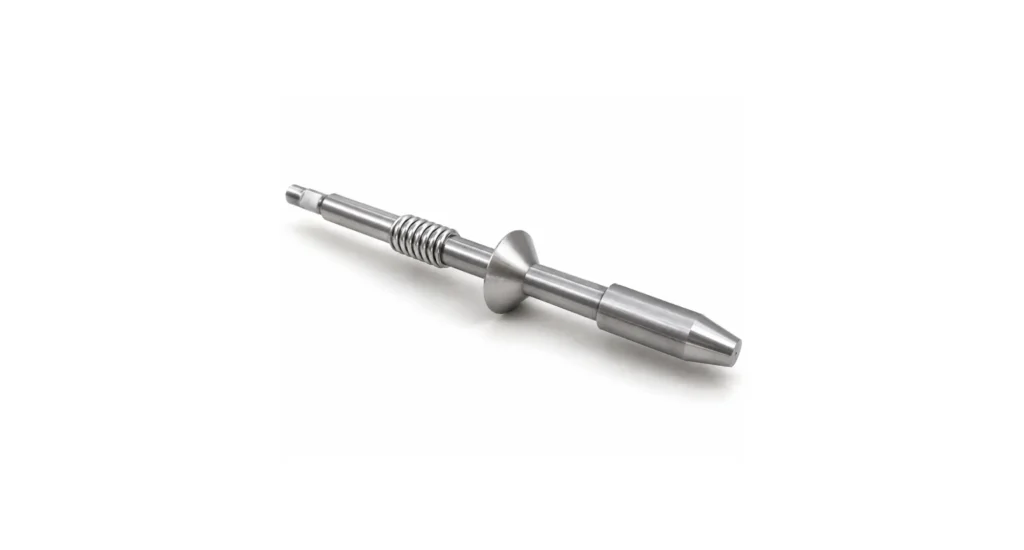


Global vetted network delivers high-quality CNC parts to your specs, every time.
Precise custom sheet metal components, advanced techniques, global network.
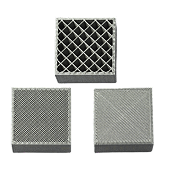
Cutting-edge rapid prototyping & production, accurate custom parts from digital designs.
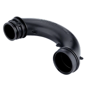
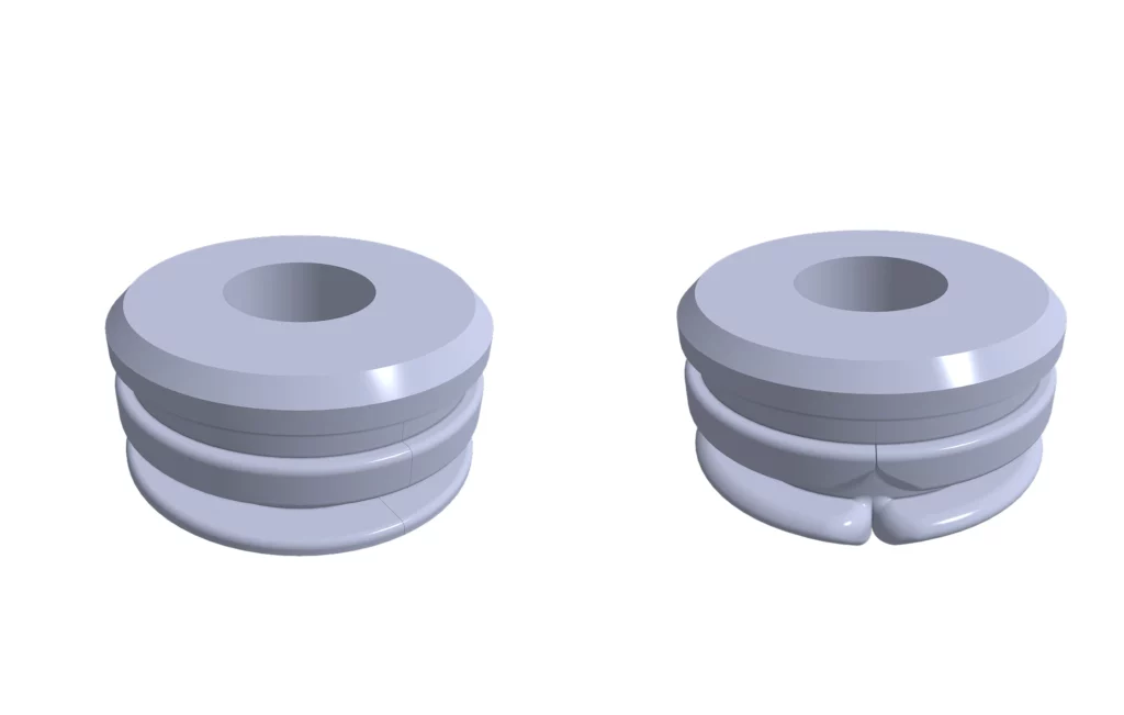
Global network, precise & efficient custom injection molded components, exceptional quality.
CNC Machining Service
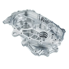
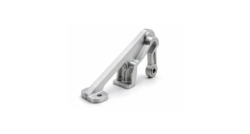
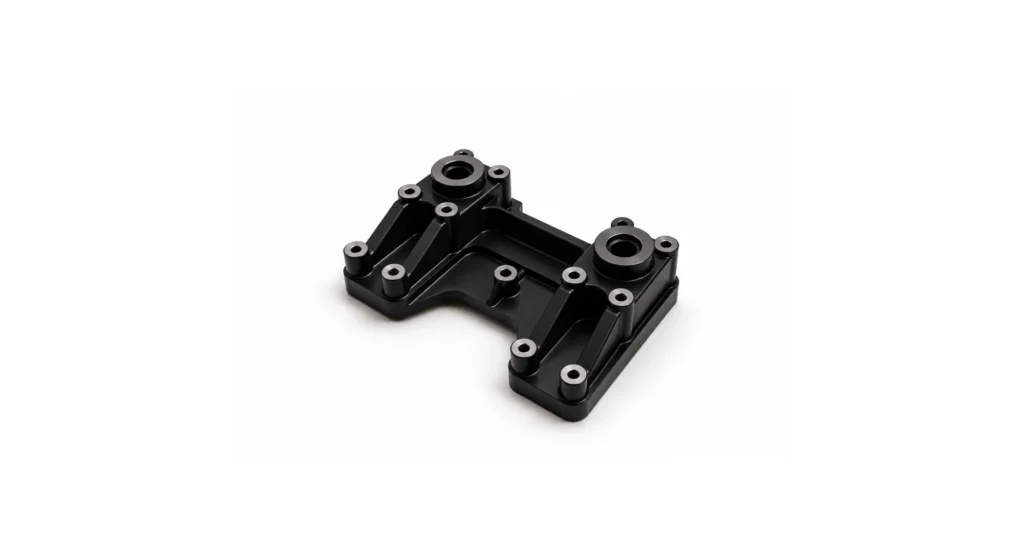
Multi-axis precision milling for complex geometries
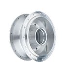
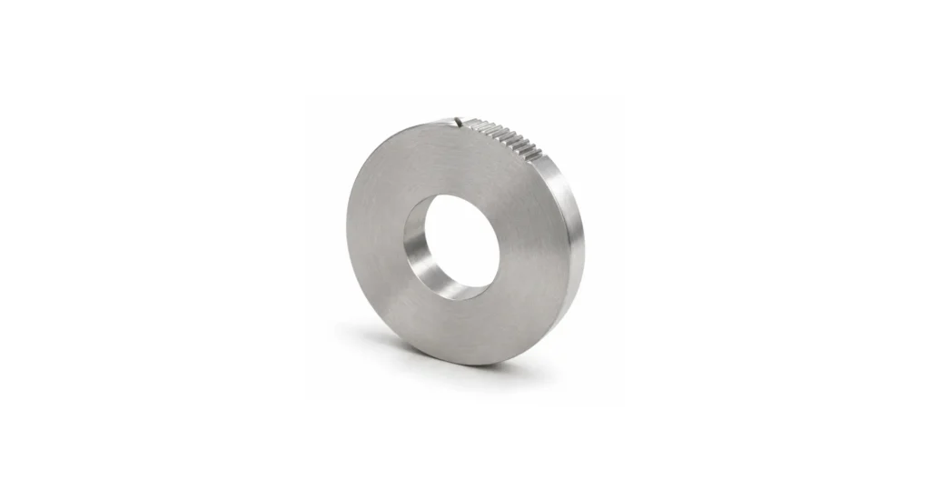
High-accuracy turning for cylindrical components
Sheet Metal Service
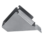
Custom brake-formed profiles, consistent angles
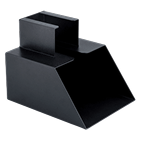
Laser & waterjet cutting for precise contours
3D Printing
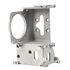
Rapid thermoplastic prototypes, fast turnaround
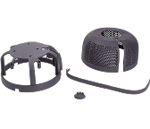
Complex nylon parts, no supports required
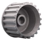
Ultra-smooth, high-detail resin models
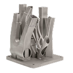
Production-grade parts, uniform properties
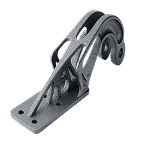
Full-density metal parts, structural integrity
Injection Molding
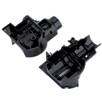
High-volume plastic parts, repeatable precision
Rigid substrate with soft-touch outer layer

Metal inserts encapsulated for reinforcement
Qualified US network delivering mission-critical parts from prototype to full-rate production.
Custom parts from weekly prototypes through to reliable volume production.
Consistent suppliers, costs that drop every lot, programs that hold.
Upload files. Get quotes. Connect with vetted manufacturers.
Track orders, monitor suppliers, and control revisions – all in one place.
Collaborate on quotes and orders with suppliers and your team.
End-to-end service removing supply chain friction from onboarding to delivery.
Metal Injection Molding (MIM) is one of the most powerful – and unfortunately misunderstood – manufacturing processes available in the increasingly complex manufacturing toolkit. Two core realities define the ability to exploit its real, practical benefits.
These are not exaggerations – they emerge directly from how MIM works and how it is often underexplained by service providers. Unlike CNC machining or even plastic injection molding, MIM is not a shaping process where geometry is directly controlled. It is a multi-stage transformational process – feedstock preparation, molding, debinding, and sintering – where the final geometry only emerges after irreversible physical changes that are second, and in some ways third order events derived from geometry.
That means success or failure is not determined during production – it is designed into the system in committed and typically unalterable decisions, early in the process.
MIM sits between injection molding and powder metallurgy – but in various regards, it behaves unlike either.
| Process | Geometry Control | Iteration Cost | Failure Visibility |
|---|---|---|---|
| CNC Machining | Direct (cut what you see) | Low | Immediate |
| Injection Molding | Predictable shrinkage | Moderate | Early |
| MIM | Emergent (multi-stage transformation) | High | Post-sinter |
In CNC, geometry is explicit. In MIM, geometry is predicted – and that prediction depends heavily on multiple interacting variables that are mostly absent from the design process:
This creates a path-dependent system where early assumptions propagate through every stage, often risking amplification throughout.
Most quoting systems operate on the basis that geometry can closely define cost
This works for:
But MIM process, precision, and cost depends on variables not present in CAD:
Typical shrinkage is 15 to 20% volumetric (≈5 to 8% linear). But it varies in complex and interactive ways with:
This makes shrinkage a spatially variable deformation problem, rather than a simple scale factor.
Automated quoting systems assume:
Tool cavity = geometry × uniform shrinkage
Reality is very different:
Tool cavity = geometry + experience-based distortion compensation
The compensation for these factors is supplier-specific, experience-driven, and typically non-linear. The result of this is that geometry-only quotes are structurally unreliable, and generally serve as an attention capture tool, either pricing for worst case, or pricing to introduce ‘surprises’ downstream, once the client is “invested” in the supplier relationship.
The quality of outcome in MIM is a direct result of the DFM status of the design and the integrity and quality at each stage in this multi-criticality process, governed by path dependency.
Once material is specified, shrinkages analysed, and tooling is cut:
During sintering heating and fusion rates can be irregular, affected by section thickness:
This creates:
These are not process errors, they are design consequences built into the part, the tooling or the material selection.
In most processes, failure appears early. IIn MIM, failure appears after every part of the process is committed:
This creates:
A single incorrect assumption can cascade through weeks of processing before becoming visible. It is because of this risk that outset-cost sensitivity must not be allowed to hold the controls in supplier and process selection and execution.
Various possible faults arise in the high temperature sintering that is so critical in integrating bonded powder into a final, high density whole.
These define flow, fill, density, and shrinkage behavior.
This defines:
Changing feedstock post-tooling is often impractical, beyond finesse adjustments.
These aspects can disrupt outcomes in potentially harmful ways, often exposing fundamental design issues in unexpected ways.
While design dominates, modern MIM systems can partially recover:
However, these are minor adjustments or corrections, but rarely cures for fundamental issues. They operate and control within narrow bounds.
Acquisition of the knowledge/experience-shortcuts that are intrinsic to DFM is perhaps more important in MIM designed parts than in any other area. The difference between success and failure of the process and reducing parts will lie in early decisions that are a minefield for the unwary.
Seek support, validate that the experience you’re drawing upon is valid, relevant, and unbiased. Seek to:
This is the highest-leverage intervention. Do these things well, and 70% or more often the process risk is minimized.
Evaluate suppliers based on real data, timely communications, appropriate experience and a good portfolio of relevant projects. Look for:
Plan well, with good support, and your first parts should be good. Probably not great – but good! Be ready for process and tooling adjustments that double the original tooling time budget and add 25% to the cost.
If you’re early, take the win. You probably will need the extra budget, though.
If a quote ignores:
It is structurally unreliable. Get the price as a reference point, but don’t have high expectations of the supplier.
Platforms like Jiga improve outcomes by acting as right-hand support. rather than middle-man.
Make sure you are:
Before RFQ, ask yourself:
If not, the risk of a bumpy road and potential for a poor result is high.
The exclusions for use of MIM are not complex and few edge cases exist. Avoid MIM when:
| Defect | Stage | Primary Cause | Pre-Tooling? | Adjustable? |
|---|---|---|---|---|
| Flash | Moulding | Pressure/tool fit | Partial | Yes |
| Short shots | Moulding | Thin sections | Yes | Partial |
| Cracking | Debinding | Binder system | Yes | Limited |
| Warpage | Sintering | Geometry | Yes | Limited |
| Porosity | Sintering | Temperature/time | Partial | Yes |
The two core truths reinforce each other:
MIM is not a process you optimize after the fact. It is a process you get right before it begins, or expect difficulties downstream.