What is CNC Machining?
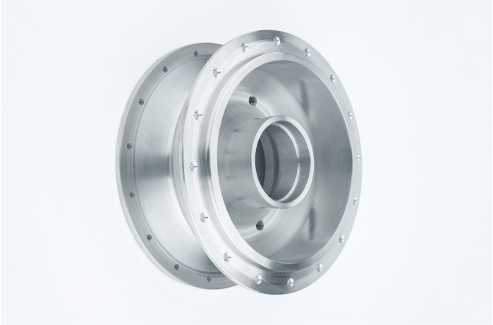
It’s a vanguard process in the rapid-prototyping and low-yield/high-precision manufacturing sector.
CNC machining allows for the rapid but highly accurate construction of projects from materials that are not suited to other types of rapid prototyping manufacturing, such as 3D printing.
In this article, we’ll be taking a deep dive into CNC machining to create a complete guide to this cutting-edge process.
What is CNC (Computer Numerical Control) Machining?
The term machining generally refers to the use of a cutting tool used as part of a controlled material removal process to render a workpiece to a desired final size and shape.
Traditionally this was done by a skilled technician. If you think of an old-school carpenter with a lathe and a chisel set, you’re not far wrong.
This manual form of machining is still used today and is normally referred to as conventional machining. The technician doesn’t need to wield the tools anymore and can direct and control machining tools via a computer interface.
What makes a machining process conventional is that a human determines the location and intensity of tool contact.
By comparison, computer numerical controlled machining uses software to render a 3D design into instructions for a set of computer-controlled machining tools. The software and computer-controlled tools then conduct the machining process without the need for significant oversight.
Essentially, in CNC machining, the software determines the location and intensity of tool contact.
Basic Components
At the most basic level, CNC machines can be broken down into three main sections, including:
- The software – The software installed on a CNC machine interprets the 3D CAD design and translates this into two codes that the machine control unit can understand, miscellaneous code (M-code) and geometric code (G-code).
- The machine control unit – The machine control unit is programmed by the M-code and G-code which provides it with the movement and speed of cutting heads and other pertinent information such as the use of coolant, tool change, and when the current program stops.
- The processing equipment – The processing equipment represents the machine tools that perform the various machining operations, which we’ll cover in greater detail later in this article.
CNC Machining Process Overview
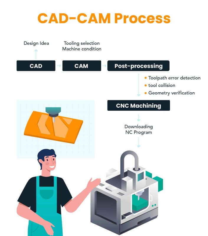
The process of creating a CAD design, translating it into a CNC program having the machine use that program to manufacture a part can be broken down into four basic steps, including:
Designing the CAD model
The CNC machining process starts with the creation of a 3D solid CAD design. While the creation of a CAD model is beyond the scope of this article, we will cover some basic design principles that should be adhered to when designing for CNC.
The first step in designing a part is deciding on what type of geometry will be required. With 3D solid models, surfaces are usually used instead of solids because they take up less space and offer many more editing options which can lead to faster modeling times.
Once an appropriate geometry has been defined, the next step is deciding how much material needs to be removed from each surface.
This process involves several steps: First parts have to be exploded so that individual surfaces can be selected; extruded or revolved surfaces must then be created and the required pattern applied to them.
This step can be very time-consuming depending on the number of patterns that are being used, and therefore requires careful planning to ensure they don’t obstruct each other. Once all the surfaces have been defined, a cutting tool path needs to be set up so that it is possible to machine the part.
2D vector CAD programs such as AutoCAD or BricsCAD are rarely used for CNC work since they cannot be easily adapted into 3D models; however, these 2D programs do provide an option for mapping out what a final design will look like in advance.
3D modeling software such as Solidworks and Autodesk Inventor often contain features specifically tailored towards the CNC machining industry.
The 3D design will also contain information on the required tolerances for the machining process. This is generally included as GD&T, which stands for Geometric Dimensioning and Tolerancing.
GD&T is a symbolic language that provides the geometrical product specifications, tolerances, and geometric tolerance for a 3D design.

Benjamin S

Mechanical Engineer
"I wish this existed years ago!"
Jiga is the best way to get the parts you need, when you need them.
Converting the CAD file to a CNC program
Once the CAD file has been completed, it must be turned into G-code, which is the language that CNC machines use to ‘speak’.
The conversion process involves sending the CAD file through a CAM (Computer-Aided Manufacturing) program. These programs are specifically designed for converting CAD files to G-code and are loaded onto a computer attached to the CNC machine.
There are two methods of converting using CAM software: robot or manual method. Which method is chosen depends upon the CNC machine that will be doing the cutting.
The robot method is for machines with a dedicated robot such as a Haas, Doosan, or Mazak.
This method requires CAM software supplied by the CNC manufacturer and uses proprietary language. This ensures compatibility from one computer to another but can only be used on machines made by that company.
While this may seem limiting, it actually stores all tool paths in formats that are useful to anyone using any brand of CNC because they are common codes. These files can even be used for basic nesting purposes if needed.
The manual method has no dependencies on special software and works with any CAD/CAM system that outputs g-code.
Preparing the CNC machine
Once the CAD program has been converted into a CNC program it can be uploaded to the CNC machine. The program provides both the miscellaneous code (M-code) and geometric code (G-code).
The geometric code (G-code) controls the movement and speed of cutting heads while the miscellaneous code (M-code) covers any other relevant data that is not directly related to the movement and speed of cutting heads.
This might include the use of a coolant or something as basic as when the program starts and ends.
Executing the machining operation
Once the CNC machine has been prepared with the G-code and M-code, the machining operation needs to be executed. After setting up the proper parameters (work coordinates, cutting tool, feed rate, spindle speed, etc.), the G90 command must be executed.
This tells the machine that all subsequent commands are to reference absolute machine coordinates rather than relative movements.
The G20 (inches) or G21 (millimeters) command can then be set depending on the units of measure desired for the execution of the program and indicate information about material conditions (thickness and size).
The next step is to execute an approach movement in order to position the tip of the cutting tool at a point where it can begin machining operations. The most common form of approach is a straight line from some position in space directly towards one’s destination point.
While this is usually the most simple and straightforward approach that can be used, there are many cases where it is necessary to use a different kind of approach.
For example, the operator may want to use a circular arc rather than a straight line or a helical approach in complex three-dimensional shapes.
Approach movements are typically executed with the coordinates being relative to some point on the C axis (which might be different from the machine origin) so as not to interfere with the operation of another machine tool sharing the same coordinate system.
Once the approach has been set, the machine will execute the program, using the movement set by the G-code to remove material from the workpiece.
Common CNC Machining Operations
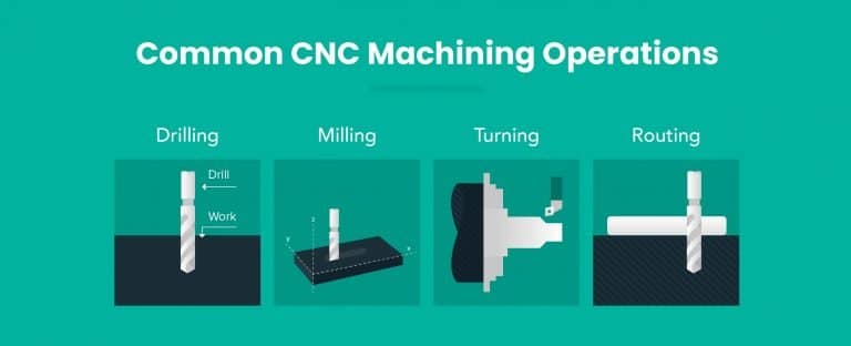
To remove the right amount of material from the workpiece to the correct dimensions and tolerances, CNC machines use certain basic processes, including:
Drilling
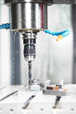
Drilling is the process of creating cylindrical holes in a workpiece by using multi-point drill bits.
CNC drilling can produce vertically aligned holes with diameters equal to that of the bit used, but angular drillings are also possible through specialized machine configurations and devices.
Drilling has counterboring (creates countersunk features) and countersinking capabilities as well.
These operations produce holes with diameters smaller than the drill bit diameter and larger openings at the bottom of a hole to allow for flush seating of subsequent components or fasteners such as screws, bolts, and pins respectively.
Milling
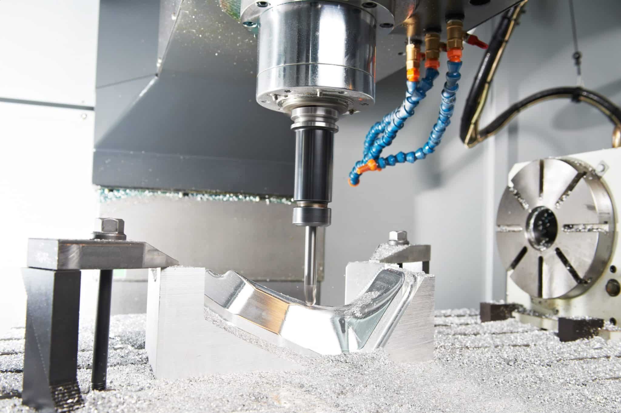
The process of milling is a machining technique in which rotating multipoint cutting tools remove material from the workpiece.
In CNC milling, there are two ways to feed the machine: either by feeding it in the same direction as that of the tool’s rotation or opposite to its rotational movement.
The process can cut shallow, flat surfaces and flat bottomed cavities into the workpiece, also known as face milling. It can also perform peripheral milling in which it cuts deep cavities, such as slots or threads in the part.
Turning
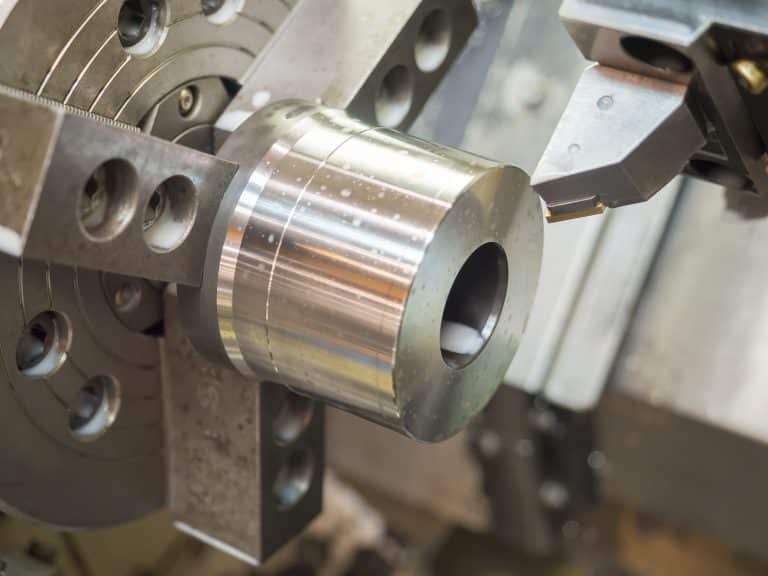
Turning employs single-point cutting tools as part of a machining process that is used to remove material from the rotating workpiece.
In CNC turning, the machine—typically a CNC lathe machine—feeds the cutting tool in a linear motion along the surface of rotation on top of it removing any excess until desired dimensions are reached.
Operational capabilities of the turning process include boring, facing, grooving, and thread cutting.
When it comes down to a CNC mill vs lathe for manufacturing parts, milling with its rotating cutting tools works better for more complex parts.
However, lathes with their rotating workpieces and stationary cutters are faster at working on rounder objects in particular while being just as accurate if not more so than mills when it comes to simple tasks such as drilling or reaming
Routing
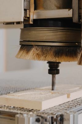
Routing is used for the precision cutting of various materials such as wood, composites, aluminum, steel, and plastics.
This process is often used when creating joinery such as mortises or tenons due to its ability to create extremely accurate cut lines time after time
In comparison to laser cutting, CNC routing is very cost-effective, although laser cutting does produce a noticeably cleaner edge and is able to produce a level of precision not available with a friction cutting method.
Types of CNC Machines & Tools
Rather than one single CNC machine or tool, there are multiple options available that specialize in different machining processes, including:
CNC Milling Machine
CNC milling machines are usually used for subtractive manufacturing (material removed by the machine) processes such as engraving, jig grinding, and boring.
Mills are normally classified in two ways: by the shape of the table and by spindle orientation. The overall size or shape of the table is relative to the work envelope and the maximum weight it will hold.
In terms of spindle orientation, they may be either gantry mill or overhead bridge mill.
A bridge mill is mounted over a stationary table on a rack and pinion carriage system to move it across each axis while the Z-axis prevents movement in the Z direction.
A gantry mill, on the other hand, has a moving gantry that travels along two rails above and across the machine which moves the table through each axis.
With this movement, there is no need for a lift or bed to move within an x – y plane as with bridge mills; however, most bridge mills are also able to function as a gantry mill with proper work envelope and capability.

Alan B.

Mechanical Engineer
"Hands-Down the Best Platform and Partner for Fast, Quality Parts"
Jiga is the best way to get the parts you need, when you need them.
CNC Lathe Machine
With a CNC Lathe, the task of positioning the cutting tool along three axes is done by a computer numerical control (CNC) system which also controls the spindle, feed rate, etc., typically using cams or lookup tables.
This is superior to a traditional lathe because it can be used for different lathing operations, such as facing, turning between centers, and screw-cutting.
There are two types of CNC Lathe Machines; a “full function” CNC Lathe Machine or a Milling/Turning hybrid machine.
A full-function CNC lathe machine typically has all of its movements under computer control including the spindle motor and direction (feed rates).
On the other hand, a milling/turning hybrid machine typically lacks automatic control over the rotation of the workpiece.
Electric Discharge Machine
Electrical Discharge Machining (EDM) is a controlled metal-removal process that is used to remove metal by means of electric spark erosion.
The process is used when the material to be removed contains no convenient tooling features, such as drilled holes or pockets. EDM can also remove material from a part that would otherwise be considered scrap.
Electric discharge machining can be divided into two main subcategories: Wire EDM and Die Sinking EDM.
The terms wire cut and sinker are used for historical reasons since the wire electrode has been changed to another type of electrode.
Wire EDM uses an electrical charge which runs between 2 electrodes. Material is dissolved by arcing across the gap in between electrodes in U-shaped grooves called ‘kerf’.
In Die Sinking EDM, the wire is replaced with a die. The difference being it uses the tool to produce the cut. This method can be faster but depends on having round inserts that are used for each part geometry.
CNC Plasma Cutter
In CNC plasma cutters, inert gas like compressed air or nitrogen is used to propel a high-energy flame of non-luminous plasma toward the material being cut.
The jet from the plasma torch cuts through electrically conductive materials by melting and evaporating away the material at extremely high temperatures (4200 K).
This typically makes it ideal for cutting metals in sheet form, since molten metal can be quickly moved before it has time to cool down.
CNC Router
A CNC router is a computer-controlled machine that has the ability to move the cutter head and control the motion of a workpiece in all directions. The motion can be programmed by utilizing various software packages such as CAD/CAM or CAM2, which controls the movement of the X, Y, and Z-axis.
The three axes along with their respective axis motors run at high speeds and are controlled via stepper motor drives. This allows for precise cuts across a wide range of materials.
Even though a CNC router uses many of the same components as other CNC machines like mills and lathes, it features unique components as well. One unique component is an automatic tool changer system that allows for quick swaps between tool heads, for example.
CNC Axes
Modern CNC machines are generally split into two types; 2-axis and 3-axis machines and multi-axis machines
2-axis and 3-axis machines
3-axis mills are the most common CNC machines. The 3-axes refer to linear motion in the X, Y, and Z axes. In milling, a tool spins as well for cutting purposes.
CNC Lathes often only have two main motions with one stationary tool that moves linearly along X and Y while also having the workpiece spinning around.
2-axis and 3-axis machines can struggle with complex geometry due to restrictions on undercuts or other factors making internal geometry challenging.
Multi-axis machines
A multi-axis CNC machine is any machine with more than three axes. When you start adding more axes, it becomes possible to have the tool head and machine bed rotate automatically without human intervention. This saves time by removing manual steps in between operations.
The easiest way to do this is through indexed CNC machining where rotation only occurs during setup or when changing tools. It typically involves using a 3 + 2 axis of movement for simplified setups and programming.
An even higher level can be achieved with continuous 5-axis machines that move on all linear (X, Y & Z) coordinates while also rotating about both their own “Y” as well as the workpiece’s fixed “Z”.
Machines with more than 5-axes have increasingly higher accuracy rates and time efficiency. For example, a 12-axis machine has two heads that both allow linear motion along the X, Y, Z axes as well as rotation around each of those.
Types of CNC Machining Support Software
We’ve already mentioned some of the software used to create 3D designs and translate them into the code that instructs a CNC machine. These include:
CAD
CAD or computer-aided design is the first step in the CNC manufacturing process. A computer-aided design package will allow the user to create a drawing specific to the machine and material they are using.
CAD software is used for importing 2D drawings, creating 3D models and surfaces, manipulating images with photo editing packages such as Photoshop, generating toolpaths for CAM packages, and simulating future processes.
CAM
A CAM package consists of an application that takes a user-created 3D design created in CAD software and translates it into instructions a CNC machine can understand.
These instructions come in the form of G-code, which controls the movement and speed of cutting heads, and M-code, which covers just about anything else.
CAE
CAE or computer-aided engineering software is often used to examine the performance and tolerances of 3D designs produced in CAD software by subjecting them to theoretical stresses as part of computer simulations.
This is a hugely important part of the design process as it allows the designers to test and set tolerances before the piece is machined.
CNC Machining Materials
The CNC machining process works with a huge range of materials, including:
Metals
Aluminum
Used in transportation, packaging, construction, and countless consumer products, Aluminum is a hugely popular metal for use in CNC machining because of its excellent strength-to-weight ratio and high recyclability.
Steel
Steel is commonly used in CNC machining because it’s tough and durable, but it is not without its drawbacks. One of the biggest issues with using steel in CNC manufacturing is that the material is incredibly difficult to machine due to how hard it is.
Layer bonding of metals such as steel also poses additional challenges because they need high temperatures and wide spaces between toolpaths in order to prevent collisions.
Stainless steel
Stainless steel is used in the CNC machining of engine valves, ball bearings, and other high-wear applications because it’s nearly impervious to corrosion. It is also the material of choice for surgical instruments and kitchen equipment that must be resistant to heat and chemicals.
A2 Tool Steel
This Tool Steel has been in use since the early 1900s and has become one of the most popular high-carbon tool steels. A2 is a water hardening tool steel that features excellent wear resistance along with good toughness and durability.
Cast Iron
Cast iron is a lot easier to machine than other harder metals like steel and is used mainly to make pots, pans, and other cookware. However, it can also be used to make gears and bushings.
Brass
Brass has excellent machinability and is commonly used for components that require a combination of strength, good wear resistance, and good corrosion resistance.
Bronze
Bronze is often CNC machined into parts bearings, washers, and brushings. The material is easy to work with, relatively cheap yet durable, and heavy in weight.
Copper
Copper has a combination of properties that make it ideal for use in the electronics and automotive industries. It is easily worked, ductile, and highly conductive.
Titanium
Titanium has a combination of lightweight and high strength that makes it a good material for building aerospace components. It is most commonly used for building airframes, landing gears, and some engine parts.
Plastics
ABS
A low-cost engineering plastic, CNC machined Acrylonitrile Butadiene Styrene (ABS) is excellent for prototypes due to its low cost and production-like qualities.
ABS can be painted or powder coated to give it more durability and UV resistance while giving it a matt finish, however certain faces may appear shiny depending on their geometry
Polycarbonate
Polycarbonate, sometimes known as PC has the benefits of being impact-resistant, heat-resistant, and flame-retardant. It has a scratch-prone glossy finish, to which anti-scratch coatings can be applied. It is also highly recyclable.
Nylon
Nylon 6/6 has excellent tensile and flexural strengths, fatigue resistance, wear resistance, low-stress relaxation, and high compressive strength. It is often chosen over metals or glass on account of its high durability and scratch resistance. Nylon also boasts good insulation properties, such as for use with electrical devices.
POM (Delrin)
A low-friction, high-stiffness material, Polyoxymethylene (POM) has a range of applications in medical devices, engines, and robotics. It’s one major drawback being the fact that it is highly flammable.
PEEK
Polyetheretherketone is often used as an alternative to lightweights metal or glass in the aviation industry because of its high toughness and low weight.
PEEK is a high-performance plastic that has outstanding electrical insulation and resistance to chemical attack and high-temperature fluids.
PPS
Polyphenylene Sulfide (PPS) is often used in the automotive, electrical, and electronics industries because of its excellent temperature resistance, electrical insulation, and stability.
Acrylic
Polymethyl methacrylate (PPMA), more commonly known by its brand names Plexiglas and Lucite is a synthetic polymer resin that is often used as an alternative to glass because it is about half as thick, yet more impact-resistant, and nearly unbreakable.
Garolite G-10
Also known as phenolic and epoxy-grade industrial laminate, Garolite G-10 is used in several areas including military, industrial, commercial, and aviation industries because of its resilience when exposed to harsh conditions.
HDPE
HDPE is used in everything from medical tubing to milk jugs and water pipes. Other plastics such as polypropylene (PP), low-density polyethylene (LDPE), and linear low-density polyethylene (LLDPE) have lower coefficients of friction, but none come close to the coefficient achieved by HDPE.
Polypropylene
Also known as PP, polypropylene is derived from petroleum and is highly resistant to solvents and chemicals, making it a common plastic for use in containers and implements.
PTFE
Commonly known as Teflon, PTFE has low surface friction, good electrical resistance, and is self-lubricating. PTFE’s non-stick properties are used in cooking utensils and for a wide range of applications from car brakes to wiring.
UHMW
Ultra-High-Molecular-Weight Polyethylene, which is also known as UHMW, is a hard plastic that is extremely tough and resistant to abrasion. It is used in the automotive industry under the brand name TENARIL®.
Ultem
Polyetherimide, also known as PEI or the brand name Ultem, is an amorphous thermoplastic material that has a really high tensile strength and very good heat resistance as well as chemical resistance.
Woods
When it comes to woods that are suitable for CNC machining, hardwoods tend to work better than softwoods.
Woods like maple, walnut, cherry, pear all have excellent internal cohesiveness across the grain and a solid even consistency.
This is important in subtractive manufacturing processes like CNC machining where the high counterforces can tear the wood apart along the grain instead of cutting through it.

George B

CTO
"Hands-Down the Best Platform and Partner for Fast, Quality Parts"
Jiga is the best way to get the parts you need, when you need them.
Materials used for finishing:
Alodine
Alodine, also known as chromate conversion coating, is used to protect aluminum parts from corrosion. Aluminum has a chemical reaction with oxygen, creating a layer of aluminum oxide on the surface of the part.
This thin natural coating is hydrophobic and prevents water from penetrating into the material, making it ideal for protecting parts that are prone to corrosion.
Anodizing
Anodizing is a chemical process that is used to enhance the appearance of aluminum (and other metals) while increasing corrosion resistance.
The process uses an electrolytic cell to create an oxide layer on the exposed surface by going through different voltage levels. The oxide layer can be built up to different thicknesses to give greater resistance to corrosion.
Black Oxide
Black oxide is a conversion or surface coating that is created by heating in a chamber filled with hydrogen sulfide gas and sulfuric acid vapor to 370 degrees Celsius. The black oxide coating then forms a barrier that protects the metal from further corrosion.
Electroless Nickel Plating
Electroless nickel plating, also known as ENP, is a plating process that increases protection against corrosion and wear, improved conductivity, reduced friction, enhanced lubricity, extended part life, and easier cleaning.
Electropolishing
Electropolishing is a common finishing process for a variety of metal parts electricity and an acid chemical bath to remove surface imperfections.
Media Blasting
Also known as sandblasting, media blasting uses a high-pressure jet of media such as glass or plastic beads to apply a uniform matt surface to finished parts.
Nickel Plating
Nickel plating is commonly used to prevent corrosion of metal objects, for decorative reasons, and to prevent bacterial contamination. The nickel plating is applied by submersion in a plating bath that contains nickel salts.
A current is passed through the bath which causes the metal ions in the salt solution to be deposited onto the surface of whatever object is being plated.
Passivation
Passivation is a chemical reaction in metal objects which prevents further corrosion by creating an oxide coating on the surface of the metal and then converting it into a metal phosphate before sealing it with a zinc or manganese compound.
Powder Coating
Powder coating involves applying a thermoplastic or thermoset polymer to the surface of a, normally metal, object, using an electrostatic application to create a scratch and corrosion-resistant layer.
Advantages of CNC machining
- The fact that CNC machining can provide the accuracy and precision required by even the most demanding of tasks.
- The finished products are capable of being made to very tight tolerances, so much so that they may be practically impossible to make by hand.
- One area in which CNC machining excels is in making those parts that must have a high degree of symmetry. This symmetry allows for uniform load distribution, which means that the component will handle stress far better.
- CNC machining is machine automated, which helps reduce labor costs and manpower.
- In general, the machines can be set up faster and with fewer people than a manual operation. This also makes it possible to run several jobs at once on the same machine without much additional set-up time or workforce requirements
- The workpieces are often more precise since multiple cutting passes can be programmed on the machine. This helps improve productivity and make parts with high tolerances possible in one production run.
- Compared to other manufacturing processes CNC machining is quick and cost-effective, which makes it hugely effective for rapid prototyping.
Disadvantages of CNC machining
- As a general rule, CNC machines are far more expensive and harder to set up than manual milling machines.
- Specific training is needed to operate modern milling machines.
- Compared to other manufacturing processes like injection molding, CNC milling is comparatively slow and wasteful.
Applications for CNC Machining in different industries
CNC milling has a range of applications in different industries that include automotive, aerospace, and many other sectors.
Dental
The dental application of CNC machines made its debut in 1870 when a French engineer had high-quality dental prosthetics milled from wax models. These were the earliest attempts to produce precise and detailed parts through numerical control milling.
CAD/CAM is now a digital process used by dentists all over the world to produce prosthetics and orthodontic appliances that are customized to suit individual patients.
Automotive
CNC milling is commonly used in the automotive industry for the manufacturing of prototype parts. Often, low tolerances and small production quantities make this subtractive manufacturing process crucial for the success of a product.
Typically, aluminum or CFRP is used as material for milled prototype parts. There are some limitations when it comes to prototyping with these materials which can be removed by combining 3D printing with CNC milling.
Medical
The medical industry has a range of applications for CNC machining technology and 3D printing.
The rise of these two technologies has enabled makers to create novel medical devices, including custom prosthetic limbs and orthotics, as well as new types of implants which can be designed specifically for their intended patient’s body shape.
Aerospace
Significant amounts of CNC milling is used in the aerospace industry for precision machining, tooling, and mold components. For example, the Airbus A350 XWB used more than 1000 different milled parts in its structure.
Rapid prototyping
CNC milling machines are commonly used in rapid prototyping because they can quickly produce 3-dimensional objects from a computer model.
These 3-dimensional objects can be rapidly produced with very specific tolerances and geometries, which is ideal for the kind of iterative process seen in rapid prototyping.
Robotics
Unsurprisingly, the high accuracy of CNC machining makes it an ideal manufacturing method for the robotics industry, where the need for speed and precision is strong. And with robot components becoming smaller every day, CNC machining has come to show its full potential in this industry.
By employing CNC machining as a manufacturing option, robotics companies can produce even highly accurate and durable parts more efficiently and more cost-effectively than with the use of injection molding, 3D printing, and traditional machining processes.
CNC Machining in Production
Outsourced CNC machining has become a staple of manufacturing in some industries. Companies that produce low-volume, high-complexity work turn to the process as a way of keeping costs manageable and ensuring deadlines are met.
This is particularly true of companies involved in the rapid prototyping process because they are often creating high-complexity parts that would require significant investment in in-house casting and machining equipment.
Instead, companies can make use of platforms like the Jiga marketplace to seek out CNC machining shops to produce high-quality prototypes to exacting specifications for them.
With Jiga, you are able to get rapid expert feedback on your order without needing to place the order first. We handle all of the shipping and delivery issues and act as the go-between for you and the manufacturer, meaning you’ll enjoy the simplicity of only ever having one contract.
We’ll also hold your money in escrow until your parts have arrived. With Jiga, you’ll only ever pay for the parts you have in your hands.
The Current Trends and Future for CNC Machining
While, as we’ve mentioned, CNC machining has its roots back in the 1870s, the manufacturing process is still evolving. Some of the current trends that are pushing CNC machining into the future include:
The Internet of Things
The internet of things has manufacturing applications such as remote monitoring, total machine shop optimization, and predictive maintenance.
This means that more CNC machines can be run more efficiently and with fewer operators, reducing overhead costs and passing the savings onto the customers.
Smart devices can also be used in manufacturing to optimize material usage through computer-integrated manufacturing (CIM).
Machine tools can process materials more efficiently while increasing the quality of parts by monitoring their temperatures and other variables. This allows for leaner production runs while lowering energy costs and associated CO2 emissions.
Another application is to use smart devices in CNC machine shops that employ small-batch manufacturing. These devices can monitor the operations and provide feedback to help manufacturers streamline their processes, allowing them to take on more jobs.
Rapid prototyping and digital manufacturing
As we’ve already mentioned, CNC machining is an excellent option for the manufacturing part of the rapid prototyping process.
However, with the rise of accessible CAD programs such as Tinkercad, Trimble Sketchup, and Autodesk 123D (formerly called Kinect), more and more businesses and individuals are able to take advantage of the benefits of CNC machining without the need to buy their own CNC machine.
With these programs, it is becoming increasingly easy to produce a CAD design for a physical part that can then be sent off to be manufactured by someone else.
This means that smaller startups no longer have to worry about minimum order amounts and manufacturing overseas. They can simply produce a CAD model of their design and use digital manufacturing platforms like Jiga to have it manufactured by a CNC machine shop in their local area.
This rapid, local, and digitized design and prototyping process means more products getting to market than ever before.
New CNC Technology
While CNC machines might have got their start in the 1950s, the technology is constantly evolving, and new, more effective machines are constantly coming onto the market.
Machines now have up to 12-axes. More axis of movement is provided on a multi-axis machine than a standard single or two-axis machine. Having more axes enables machining complex and unique shapes and helps achieve greater accuracy, as the number of variables reduces drastically when there are multiple rotational axes.
CAD and CAM software also continues to evolve, becoming more affordable and widely available. This allows for more efficient programming of multi-axis machines.
Advanced CAM software also offers simulation tools that show how a part will machine before it is actually machined, leading to smoother cutting and decreased touch time. This also allows for greater efficiency when machining multiple parts at once since all features are programmed in advance.
With these evolutions, CNC machining is cementing its reputation as an adaptable and reliable manufacturing method that offers a huge range of benefits to creatives at all scales, from milling the parts for a commercial airliner, to creating the prototypes from the next market disruptor.
