
Design for injection molding is a multifunction role that requires an experienced and calm approach from the designer, balancing the often competing and divergent needs of product function, aesthetics, manufacturability, moldability, QA and end user appreciation of the product.
Injection molding is a versatile and widely used manufacturing process for producing cost-effective plastic and sometimes metal parts with precision. It involves injecting molten material to fill a mold cavity, allowing the material to cool and solidify and then ejecting the finished part.
Material selection – Injection molding can process a wide range of thermoplastic and thermosetting polymers. A key design aspect is the selection of polymers and additives.
Mold design – Molds are hardened steel and consist of stacked plates, cavity, core etc. They include channels for fill, cooling, vents for air, linear bearings, ejector pins and other features.
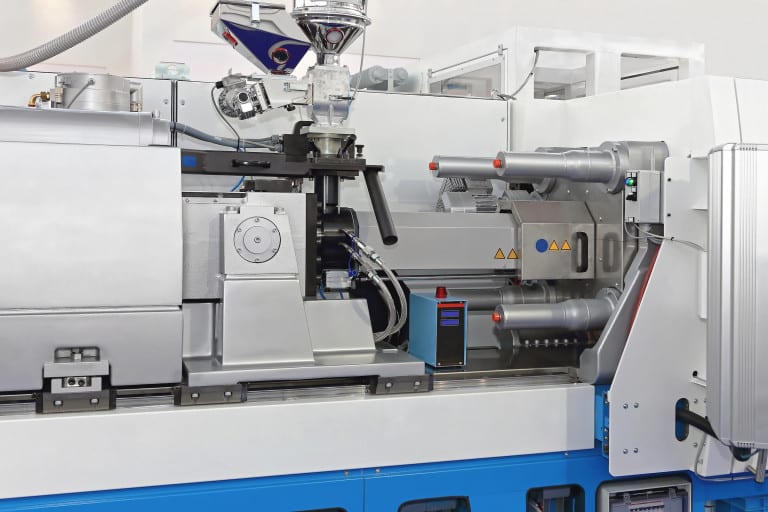
Mold machine – Molding machines have a hopper for material feeding, a heated barrel for melting the material, tool clamping means and means to drive the charge into the mold.
Injection – The molten material is injected into the mold at high pressure and fills the cavity, reflecting its shape.
Cooling – Water flows for cooling of the material, minimizing cycle times.
Ejection – After solidification, the mold opens and the finished part is pushed out.
Injection molding is suitable for high-volume industries and for complex parts with tight tolerances.
Design guide: key design considerations
Wall thickness
Designing injection-molded parts with the appropriate wall thickness is crucial for ensuring manufacturability and maintaining part quality.
- Maintain uniform wall thickness wherever possible. Consistent wall thickness promotes even cooling, reduces warping, and minimizes sinking.
- Determine the minimum acceptable wall thickness based on material properties and part geometry. Considerations such as melt-flow and welding as well as part strength can be heavily influenced.
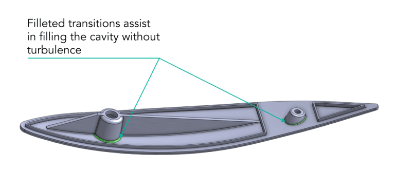
- Ensure that material can flow evenly throughout the part. Avoid abrupt changes in wall thickness, sharp corners or sudden transitions as these can lead to flow marking from turbulence or poor welding.
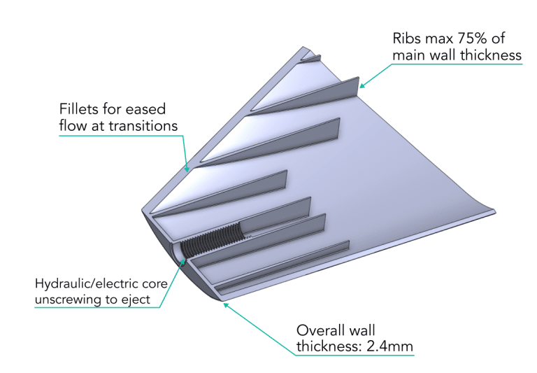
- Design ribs and bosses with thinner walls than the main body of the part, to avoid sink marks. Typically, ribs should be below 75% of the adjacent wall thickness.
- Ensure draft angles are appropriate, particularly on deep features. Consider that walls that are drafted on both sides must be at least sufficiently thick at the narrowest, and not liable to cause distortion/sinking at their widest.
- Avoid extremely thin sections or sharp edges, as they are prone to breakage potentially will not fill properly during molding.
- Material choice can affect the acceptable wall thickness. High-flow materials may allow for thinner walls, while more rigid/engineering materials may require thicker walls.
- Consider the overall geometry of the part. Complex shapes or intricate details may require adjustments in wall thickness to maintain moldability and part integrity.
- Relate tolerances to wall thickness, as tight tolerances may require thicker walls to ensure precision.
- For parts with high cosmetic requirements, consider surface finish and texture options. Special finishes may affect wall thickness and WILL affect draft angles.
- Collaborate with mold designers to ensure that the chosen wall thickness aligns with mold design considerations such as cooling channels and venting.
- Conduct cost analyses to evaluate the impact of wall thickness choices on manufacturing costs. Balancing structural requirements with material usage considerations is essential.
Considering these factors, you can design with appropriate wall thickness to ensure manufacturability, part quality, and cost-effectiveness.
Ribs
Designing ribs in injection-molded parts requires careful consideration to ensure structural integrity, moldability and part quality.
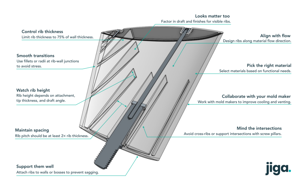
- Maintain a rib thickness of maximum 75% of the attached wall thickness. Take care of height variations and junctions between ribs to avoid broaching this limit.
- Height of ribs is restricted by the maximum attachment thickness, the minimum tip thickness for reliable fill and the draft angle required.
- Maintain good spacing between ribs to ensure even material flow during injection molding. Rib pitch should be at least two times the rib thickness to prevent flow-related issues.
- Gradually transition between ribs and adjacent walls with fileted or radiused features, where thickness restrictions allow. Sharp transitions can create stress concentrations and flow problems.
- Ribs should align with the direction of material flow to facilitate filling and reduce the risk of short-shot and scorching.
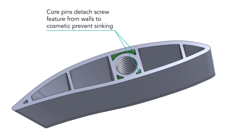
- Minimize cross-ribs and rib-intersections or add support features to accommodate them. Positioning screw pillars at rib intersections allows the screw holes forming pin to act as a core, reducing the effective thickness at the crossing.
- Ensure that ribs have proper end supports to prevent sagging or deformation during molding. Support ribs with walls, bosses or other useful features.
- If ribs will be visible on the final part, consider their aesthetic appearance. Special finishes or textures may be required to enhance the part’s visual appeal. These will require careful draft angle consideration.
- Choose materials that align with functional and structural needs.
- Collaborate with mold designers to ensure that rib features allow for consideration of effective cooling channels and venting.
By following these guidelines and conducting thorough design, prototyping, and testing processes, you can incorporate ribs effectively into injection-molded parts, ensuring both structural integrity and manufacturability.
Coring
Coring is the aspect of plastic part design that is used to control wall thickness and weight to prevent sinking. It creates a void or hollow that pares away material that would otherwise pose a shrinkage and cooling issue. This requires careful consideration and 3D analysis to maintain both the desired structural integrity and manufacturability.
- Determine the structural requirements of your part, including load-bearing areas and areas that can be cored for wall thickness control.
- Identify regions of the part with redundant material that can be cored to reduce material usage, cost and part weight without compromising structural integrity.
- Smoothly transition between cored regions and unaltered sections by using filets or sloped transitions to avoid sudden wall thickness changes, stress concentrations and flow issues.
- Apply draft angles to cored regions to facilitate part ejection and minimize friction during removal from the mold.
Radii
Radiusing or fileting of features is crucial for improving moldability, structural integrity and aesthetics.
- Fileting sharp edges and corners improves moldability, reduces stress concentrations, and enhances the appearance of parts.
- Keep your filets proportional to the size of the feature they are applied to.
- Keep the filet radii consistent throughout the part design to ensure uniformity in appearance.
- Prioritize fileting on edges near stress points, load-bearing areas or areas prone to defects like sink marks. Filets can serve well in hiding shrinkage.
- Use filets in areas where material flow may be harder, such as corners where flow stagnation or air traps can occur.
- Apply filets to the junctions between ribs, gussets and walls to facilitate fill and distribute stress.
- In complex geometries, use filets to smooth transitions between features or surfaces to improve part moldability and aesthetics.
By following these guidelines you can effectively incorporate radiusing into injection-molded parts to enhance moldability, structural integrity, and aesthetics.
Draft angles
Draft angles are essential design elements that facilitate the easy ejection of parts from the mold.
- Draft angles are tapers added to vertical walls, allowing the part to release from the mold more easily.
- Maintain consistent draft angles on all vertical surfaces to ensure even ejection.
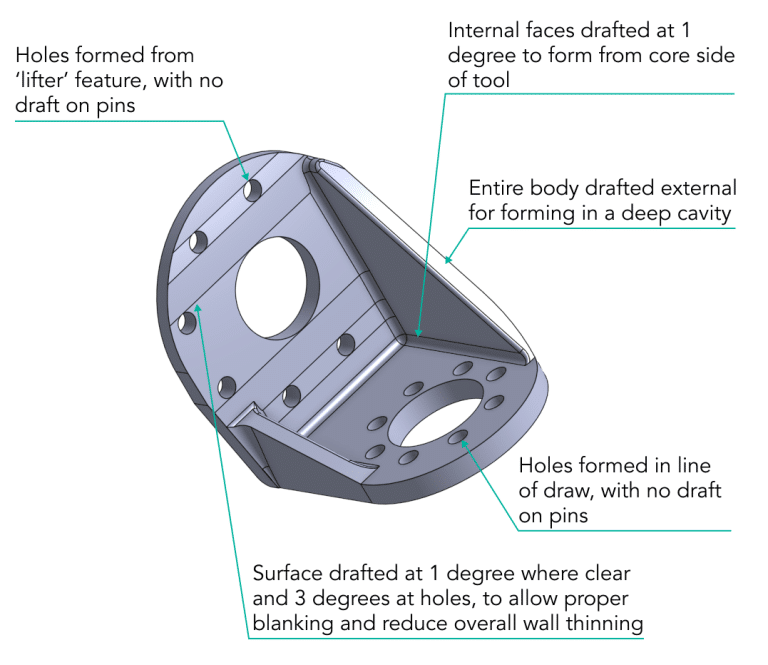
- Determine the appropriate draft angle size based on material properties, part geometry, and mold design. Draft of 1-2° on smooth line-of-draw walls and 3-5° on textured faces.
- Prioritize draft angles on critical features, such as vertical walls, ribs, and bosses, to prevent damage and ensure smooth ejection.
- Design parts to minimize or eliminate undercuts, as they complicate mold design by requiring complex actions prior to ejection.
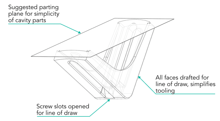
- Align draft angles with the mold’s parting line, to ensure uniform ejection forces.
- Apply draft angles to the junctions between ribs, gussets, and adjacent walls to facilitate ejection and reduce the risk of distortion.
- On cosmetic surfaces, consider using smaller draft angles or blending them into the design to minimize their visual impact.
By integrating appropriate draft angles into your part design from the start, you can optimize moldability, ease of ejection, design iterations and overall manufacturability.
Advanced design features
Effective design in plastics often requires complex features that can be challenging for moldability, or require additional complexity in tooling. These can relate to interface to other parts/assemblies, fixings, snap closures, seals and living mechanisms.
Undercuts
Designing injection-molded parts with undercuts requires careful consideration to ensure that these features can be effectively molded and released from the mold without complications.
- Clearly identify the specific features or areas of your part that require undercuts for functional or design reasons.
- Understand that undercuts typically increase mold complexity and cost, as they require additional mold actions, such as slides, lifters, or cores. Combining several undercuts can be beneficial where they lie close together – but it can also complicate the tool design in esoteric ways.
- Determine the ideal location for the parting line that will allow undercuts to be formed by tooling elements that penetrate from the obverse face – blanking. This avoids special and sliding elements in the tool.
- Design adjacent surfaces with appropriate draft angles to facilitate mold release and prevent damage to the part. Draft angles are particularly important for undercuts and for blanking faces.
- Ensure that undercuts do not interfere with each other during mold operation or part ejection. Is there enough space for the slider to operate without interfering with other features or other sliders?
- Prioritize undercuts where essential for the part’s functionality. Minimize or eliminate unnecessary undercuts to simplify mold design.
- Design the part geometry to minimize the depth and complexity of undercuts while achieving the desired functionality.
Incorporating undercuts into your injection-molded part design can be functionally necessary but requires careful planning and collaboration with mold design experts to ensure successful molding and part release.
Corners
Designing corners in injection-molded parts is crucial for achieving structural integrity, aesthetics and minimizing manufacturing challenges.
- Apply an appropriate corner radius to avoid sharps. A typical range is 0.5 to 2 times the wall thickness, depending on material and part geometry.
- Maintain consistent corner radii throughout the part to ensure uniform aesthetics and stress distribution.
- Use filets to transition between surfaces smoothly.
- On visible or high-cosmetic areas, consider larger corner radii or blended features to enhance appearance.
- Ensure that the corner designs are manufacturable without causing molding defects, such as sink marks or voids.
- Where possible, align radii with material flow to facilitate filling.
- Verify that the chosen corner designs maintain the intended functionality and appearance of the part.
Living hinges
Designing living hinges/mechanisms in injection-molded parts requires careful consideration to ensure their functionality and longevity.
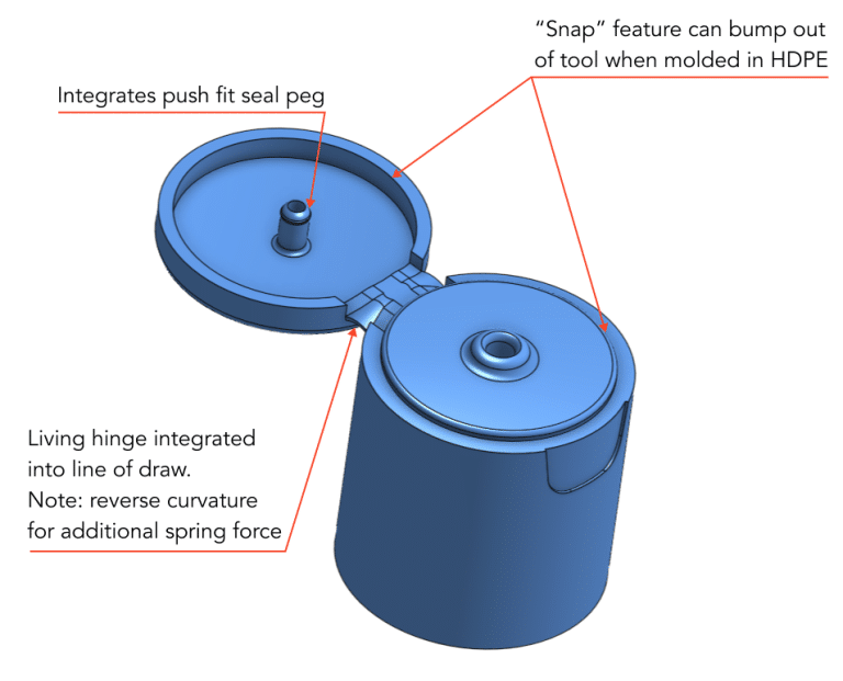
- Choose appropriate material suitable for living hinges and mechanisms. Polypropylene (PP) and thermoplastic elastomers (TPE) make great hinges.
- Typically, a living hinge should be placed along a straight axis for uniform bending. Ideally, the hinge region is the only fill path between the attached elements, for flow induced crystallinity in the region.
- Design the hinge to be considerably thinner than the surrounding material, typically 0.25 to 0.5 mm, to minimize internal shear.
- Reinforce the hinge with ribs on either side to prevent excessive stress concentration and improve durability.
- Ensure good access for the pinch tools that set the hinge after molding, where required.
- Determine the appropriate length of the living hinge zone from the intended functionality and desired bending radius.
- Ensure that the hinge curvature and radius are designed to allow for repeated bending without failure. A larger radius reduces stress and prolongs hinge life.
- Verify that the chosen living hinge design maintains its intended functionality throughout its expected lifespan. Follow durable examples and design guides as you learn the specifics.
Clips/Snaps
Designing injection-molded clips requires careful consideration to ensure functionality, ease of use, and manufacturability.
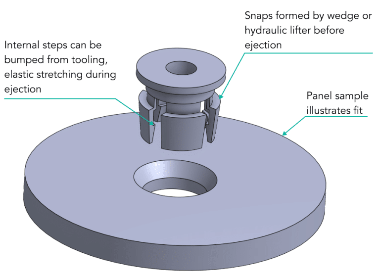
- Clearly define the purpose and function of the clips within your product to inform the design process. Answer questions such as must they be releasable, is there room for them to flex, are they the best option, can the chosen material flex reliably to deliver sufficient motion without breakage?
- Determine the appropriate clip type such as snap-fit, hook-and-loop, or friction-fit.
- Define the clip’s size, dimensions, and geometry to match the intended use such that the parts will latch securely.
- Ensure suitable tolerances and clearances to allow for easy assembly (and disassembly without excessive force if required).
- Reinforce critical clip areas with ribs or gussets.
- Design the clip to provide the necessary flexibility for secure engagement and easy disengagement and without requiring specialized tools or excessive force.
- Assess the length of the flexible element to ensure the material is not overstressed by clipping, potentially weakening the hold.
These guidelines will allo design of effective clips that provide secure fastening and ease of use while ensuring manufacturability and cost-effectiveness.
Aesthetic and functional finishing touches
In most cases, the end user’s interaction with the parts you design will be visual and tactile as much as functional. Making the part look appealing and feel high quality should not be neglected in building function and manufacturability.
Adding text and logos
Designing text and logos for injection-molded parts requires careful consideration to ensure that these features are clear, durable, and good looking.
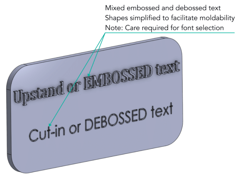
- Choose legible fonts that are suitable for injection molding. Sans-serif fonts often work well due to their simplicity and readability. Upstand text can often be more complex than cut-in text.
- Make text and logos appropriately sized and of sufficient upstand-thickness to prevent distortion during molding and to maintain clarity. These features generally look more appealing on a flat, polished and horizontal surface. Avoid such features on vertical and drafted faces.
- Avoid intricate details or high aspect ratio lines in words and images, as they can be difficult to reproduce with precision.
- Consider whether using embossed (raised) or debossed (recessed) text or logos. Debossed text is harder wearing, embossed text is often easier to read.
- Determine the location for text and logos within the part design, with care for both aesthetics and functionality.
- Plan for texture contrast between the text/logo and the surrounding material to ensure visibility.
- Avoid excessive depth and make sure to apply generous draft angles to text features for non-sticky ejection from the mold.
- Ensure that text and logos are consistently reproduced across multiple parts for branding or identification purposes.
- Recognize that many corner features will not generally be accurately reproduced because of the cutter diameter, so use smoothly clowning and corner free fonts for accurate reproduction.
- Where additional complexity, images etc are necessary, consider phot-etching or laser engraving the tool features, so that you are less restricted by what is machinable with a rotating cutter.
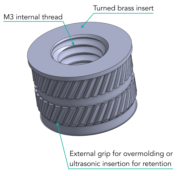
Threads and fastenings
Designing threads and fasteners for injection-molded parts requires careful consideration to ensure their functionality, reliability, manufacturability and ease of assembly.
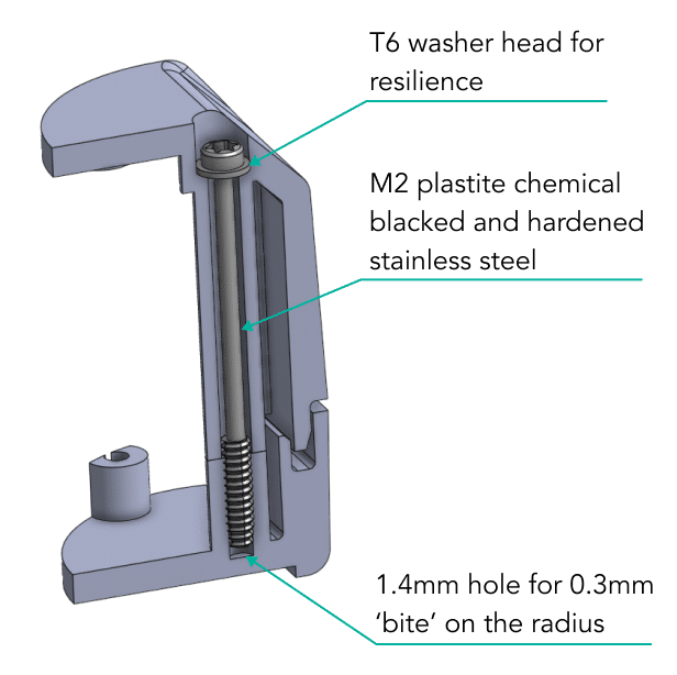
- Select the appropriate thread type, such as standard machine threads, self-tapping, or thread-forming trilobular.
- Choose thread sizes and pitches that align with the application’s requirements and ensure compatibility with standard fasteners. Deeper threads form better and offer higher pull-down and pull-out strength.
- Select the appropriate fastener style, such as screws, bolts, nuts, or other types, depending on the intended assembly method.
- Choose materials for fasteners that offer sufficient strength, corrosion resistance, and compatibility with the molded part material.
- Consider incorporating threaded bosses or molded-in metal inserts for improved thread strength and durability.
- Verify that the chosen thread and fastener design maintain their intended functionality throughout the expected lifespan of the product.
Common mistakes to avoid
Common mistakes in injection molding design can lead to defects, increased manufacturing costs, and production delays. Here are some of these mistakes and how to avoid them:
- Inadequate draft angles on vertical walls can lead to difficulty in ejecting parts from the mold and increased friction during ejection. Take particular care around blanking faces and textured walls.
- Allowing variable or insufficient wall thickness can result in sink marks, warping or part failure.
- Allowing sharp corners or edges can lead to stress concentrations, weak points and potential part failure.
- Adding complex undercuts without considering tooling issues can increase production costs and lead to molding defects.
- Poor gate placement can lead to cosmetic defects, flow imbalances and uneven packing of the mold.
- Choosing material poorly can result in poor performance or reduced part lifespan.
- Skipping prototyping and testing will ALWAYS result in costly design revisions and production delays.
- Failing to collaborate with molding experts will lead to suboptimal designs and late stage iterations.
- Ignoring parting line placement can lead to cosmetic flaws and poor moldability.
- Overly complex textures or surface finishes can complicate the mold design and increase costs.
Cost reduction practical tips
Cost reduction in injection molding design is crucial for achieving cost-effective manufacturing without compromising part quality.
- Maintain consistent and appropriate wall thickness throughout the part to prevent sink marks and optimize material usage.
- Select standard mold bases and components whenever possible to reduce tooling costs.
- Avoid or minimize complex undercuts that require additional mold actions. Simplify part geometry to reduce mold complexity and cost.
- Apply draft angles to all vertical surfaces to ensure easy part ejection and reduce wear on mold components and cosmetic faces of the tools.
- Carefully select gate type and position the gate to minimize material waste and reduce cosmetic defects. Consider hot-runners, for high volume parts.
- Choose cost-effective materials that meet the part’s performance requirements. Consider recycled or eco-friendly materials to reduce costs and environmental impact.
- Merge multiple parts into a single design to reduce assembly and labor costs, where this does not amplify tooling issues overly.
- Use ribs and gussets strategically to reinforce areas that require additional strength, allowing for thinner walls in general.
- Specify appropriate tolerances and surface finishes to meet functional requirements without unnecessary precision or cost.
- Prototype and test the design repeatedly to identify and address potential issues early, reducing costly design changes in later stages.
- If feasible, design multiple parts that can be molded together in a single tool, reducing cycle times and tooling costs. Cavities should be balanced and limited flexibility of the tooling must be accepted, for this cost saving.
- Design for optimized cycle times by considering factors like cooling channel design, part geometry, and material flow.
- For larger volume parts, explore automation options for part handling and quality control to reduce labor costs and improve consistency.
Importance of design in each stage of the cycle
Effective part design is affected by much more than simply the designer’s intent in part/product performance. It is significantly impacted by every step of manufacture, from tooling layout to mass production and quality.
For features in the design to be reproduced in the tooling, embodied in a mold that might be expected to operate for 1,000,000 cycles, careful and often iterative cooperation between tool design, component design and toolmaking are required.
The intricacies of mass production requirements and limitations must be inculcated into the designers approach, to avoid costly and cumbersome design iterations imposed by the tooling process.
Tooling design
The design of the cavity and core precisely reflect the part’s geometry and features. Complex or intricate part designs require more elaborate and costly molds.
Material selection
The choice of polymer results from the part’s design specification, to match the part’s intended use.
Mold flow characteristics
The design of the part affects how the charge flows in the tool. Complex geometries, thin walls or sharp corners can lead to flow-related issues, such as uneven filling, air traps and weld lines.
Solidification
Efficient cooling channel placement depends on the part’s geometry, to optimize cooling rates, reduce cycle times and control warping and shrinkage.
Ejection
Line of draw defines the ability for the tool to open, withdrawing the core and molding from the cavity plate. Pins then push the finished molding off the core plate to complete its removal.
Undercut features
Parts with undercuts will often require sliding tooling elements that move cooperatively to withdraw tooling features sideways, before ejection.
Tolerances
Tight tolerances or complex geometries may require high-precision molding machines.
Cycle time
Part design affects the overall molding cycle time. Fewer complex features, thick sections and threads or inserts can greatly improve production efficiency.
Part feature design
It is critical to cost effective production that the requirements of minimal cycle time, local flow, tool part-line design, gate type and application point, draft angle, blanking and much more are reflected early on in the component development.
Great knowledge and skill in understanding and accommodating manufacturing requirements are demanded of the designer, from the very first concept modeling.
Part performance
Despite the restriction imposed by tooling and mass production, there are absolute performance requirements that the component must meet in aesthetics, strength, durability etc. In a disagreement between design and production, these factors impose no-compromise requirements that must be complied with.
Assembly and post-processing
Complex part and assembly designs may require more assembly steps or post-processing. Not every desired feature or function can be translated into a moldable component, so design compromises are often required that impose additional labor costs at the assembly stage.
Good design minimizes these to maximally exploit the Industry 4.0 capabilities of CAD/CAM/tooling/molding by feature integration.
The cooperative and interlaced design of plastic parts, tooling and assembly processes plays a critical role in every stage of the design of components and assemblies. Thorough and imaginative consideration of part design as a continuum with tooling, injection molding processes and assembly is the most effective route to development of excellent, manufacturable and high performance parts and assemblies.
Material Selection
The selection of material for an injection molded part has an impact on every stage of the design, molding and assembly processes.
Concept design
Material strength, durability, aesthetics and chemical resistance influence the initial design concept, to meet its intended function and performance.
Detailed design
Material properties dictate design considerations – wall thickness, ribs/pillars and structural performance.
Tooling design
Material selection influences melt temperature, viscosity, melt acidity, shrinkage etc. and these drive mold requirements. Some materials require higher injection temperatures, some flow more sluggishly demanding thicker sections and less detail, some require stainless steel tools to resist chemical erosion.
Ejection
Material flexibility and shrinkage behavior influence how the part separates from the mold during ejection. Some materials may require additional ejection mechanisms such as sleeve ejectors, stripper plates etc. Some may even need mold release agents.
Quality control
Material properties affect the part’s dimensional stability and surface finish. Materials with high shrinkage rates may require longer cycle times to allow packing to compensate for shrinkage, or more relaxed QA requirements to accommodate this variability.
Production efficiency
Material selection can impact cycle times and production efficiency. Materials with lower melting point can enable shorter cycle times and increased productivity.
Material cost
Material costs vary significantly, and the choice of material directly affects the overall production cost. Specialized or high-performance materials may have higher material costs and impose additional processing difficulties that require specialist equipment that increases costs.
Part performance
Tensile strength, impact and fatigue resistance and chemical resistance influence functional performance and survive life and must be considered early and thoroughly.
Sustainability
Material selection also plays a role in the environmental impact of the part. Considerations such as recyclability, bio-sourcing and biodegradability are increasingly important in material selection decisions.
These considerations can carry significant production issues that must be cost-benefit analyzed early in the development cycle.
Material choice is a critical and too-often minimized aspect of designing an injection molded part. It affects the entire product development process, from the initial concept to production efficiency, cost, quality, and the ultimate performance and functionality of the finished part. The onus is on the designer to understand the downstream implications of what may seem like small decisions early in the process.
Common materials, best applications
These are general guidelines for a limited number of non-specialist polymers. Specialist materials, blends, additives and an increasing range of copolymers extends this list significantly.
The role of design in production efficiency
Design affects the molding process, and the molding process affects the design, in an iterative loop of accommodations that can optimize the part, the assembly and the product while driving down costs;
Wall thickness
Thick sections can result in longer cooling times, leading to slower cycle times and higher energy consumption.
Uneven and stepped wall thickness can cause warping and sink marks. Designing for consistent wall thickness improves moldability and part quality.
Corners and sharps
Sharp corners can lead to poor flow in the tool, turbulent flow marking, stress concentrations and structural weakness. Designing with fileted or edges improves flow, distributes stress and improves part durability.
Ribs and gussets
Ribs and gussets add structural support that helps retain stiffness and resilience, but poorly designed features can lead to sink marks or warping.effective design maintains part integrity without compromising aesthetics and allowing sinking.
Undercuts
Complex undercuts require more complex mold features such as mechanical or hydraulic slides or additional actions like hydraulic unscrewing during ejection, greatly increasing tooling complexity and cost.
Draft angles
Insufficient draft angles on vertical walls can result in cosmetic damage at ejection, as parts stick/smear rather than releasing. Insufficient draft angle where tool parts meet (blanking) causes excessive tool wear and reliability issues. Blanking draft angles must be accommodated in the part design, to avoid difficult adjustments prior to tooling.
Part material
The choice of material impacts various design and tooling considerations. Some materials may require thicker walls or additional features to meet strength or durability requirements. Some materials (POM) require stainless steel tools to handle the acidity of the molten polymer.
Tolerances
Tight tolerances often impose the need for precision tooling and increased quality control measures.
Surface finish
Part design can significantly affect the achievable surface quality.
Gate and runner design
The location and design of gates and runners affect material flow, welding and part quality.
Mold complexity
Complex part designs may require more complex, multi-plate molds with additional features or actions, increasing tooling costs and production complexity.
Assembly requirements
Component design must reflect the expected assembly processes.
Environmental considerations
Sustainable design practices, such as minimizing material waste, using bio-sourced materials and ensuring biodegradability and recyclability are important in component design.
Good component design is crucial for achieving successful injection molding outcomes. Design choices impact moldability, part quality, tooling complexity, and cost. Iterative collaboration between designers and injection molders from the concept stage is essential.
The balance between part functionality and manufacturability
Balancing the requirements of functionality and manufacturability in the design of injection molded parts is crucial for achieving a successful and cost-effective product. There are aspects to this process that must be central to the designers understanding from the start, so the down-stream requirements of mass production can be met without excessive iteration.
Early collaboration
Collaboration between design engineers and injection molding experts at the early stages of product development is essential.
Design for moldability
Designers be conscious of the capabilities and limitations of the injection molding process, to design parts that are easy to mold.
Material selection
Choosing the right material is a critical early decision that often cannot be later altered without serious consequences. Bothe function and processability must be accommodated from the start.
Geometry and complexity
While striving to optimize functionality and assembly efficiency, designers should avoid wasteful complexity that leads to manufacturing challenges and higher costs.
Tolerances and fit
Designers should specify tolerances that are achievable with injection molding processes. Good design can often compensate for lower manufacturing tolerances that suppress costs and technical challenges.
Surface finish
High-gloss finishes require manual polishing of tools, where textures can be photo etched into tool cavities and render production tolerant and more robust.
Part consolidation
Whenever possible, designers should consolidate multiple parts into a single component. This is a goal not a mission, so don;t allow this to increase complexity in ways that add to the cost burden.
Assembly design
Designing for ease of assembly can improve both functionality and manufacturability.
Testing and prototyping
Prototyping and testing allow designers to validate functionality while identifying and addressing potential manufacturability issues early in the design process. Prototype early and often, to build a great design process with assurance of success.
Environmental considerations
Sustainable design practices, such as minimizing material waste and ensuring recyclability can be integrated into the design process, to influence environmental impact.
Cost analysis
Cost analyses allow designers to evaluate the impact of design decisions on manufacturing costs.
Achieving a balance between functionality and manufacturability in the design of injection molded parts requires careful consideration of design choices, materials, and production processes.
Conclusion
The designer carries a great responsibility from the concept stage, to make decisions and drive concept directions that ease production, minimize costs, avoid late stage iterations that delay tooling and optimize part performance, price and cosmetic quality.
The knowledge required to deliver on all of these complex and interrelated aspects can only reliably be found in a multifunctional team approach and a cooperative methodology that integrates the experience of; manufacturing engineers; toolmakers; molders; QA personnel and more. The designer must be a knowledge manifold that can converge that wider teams experience into a single and carefully directed flow that makes a great product.