
CNC machining is a powerful tool that designers constantly use to achieve amazing things. Great suppliers and skilled machinists push the limits in materials, features and precision all the time.
To do a great job of designing for CNC machining, there are a few rules you should try to stick to – and when you need to break out of these limitations, take care and seek expert advice about what is practical and what is an overstep that’ll make pain for you.
Layers of Knowledge
There are plenty of design guides on the web that will advise you about features and size limits for CNC machining. Unfortunately, they mostly kind of copy each other and share the same mistakes, showing a lack of actual experience in the people reproducing the information.
We offer our own guide here, based on our own very real experience of making parts and assemblies. We have combined knowledge of well over a century total – but more importantly, we stand on the shoulders of the giants who taught us.
Aspect Ratio
This is one of the most important concepts in machining, and it needs to be stated clearly.
- In a wing section, it defines the span to chord ratio of an aerofoil.
- On a screen, it’s the width to height ratio.
- In machining it is used to define the functional diameter/thickness to depth/height ratio.
It’s all important and it can be summed up simply. Shallow, fat features or short, fat cutters are stiff. Deep, thin features or long thin cutters are flexible.
In machining, flexible is generally bad. It creates position uncertainty as tools flex and wander or parts vibrate.
- A drilled hole develops progressively worsening error in its path as it grows. This error is non linear, so small increases in depth create disproportionately greater errors in drill tip position.
- Cutting a tall, thin feature will cause the upstand part to oscillate or vibrate, likely bouncing into the cutter and being tapered by it.
- Worse still, without material remaining to support the feature, internal stresses in the upstand might cause it to bend.
In most of these advisory guidelines below, the feature depth to thickness, or cutter diameter to depth ratio will play a part that you need to consider with care, in developing your own designs.
Drilling
Drilling seems like a simple thing, but there are a whole lot of rules, guidelines and restrictions that should be closely followed, if precision is to be maintained and tools unbroken.
Depth Restrictions
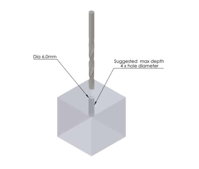
An action as simple as drilling a hole can pose challenges. First, are you going to drill the hole with a twist drill or an end mill? End mills have a flat point, so they are less reliable at self-centering. That’s ok with a 10mm diameter cutter drilling 30mm deep. But a 6mm diameter cutter, drilling 30mm deep will wander, potentially badly.
As a guide, if you want precision in the end of the hole, drill only 4 or perhaps 5 drill diameters deep with a 120° tip twist drill;
Similarly for an end mill or slot drill, 3 diameters is a safer limit;
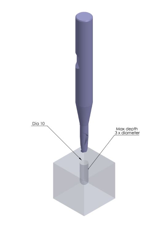
The difference in depth limit is all about precision. The twist drill has a point, forcing it to self center a little better than the flat-tipped end mill or slot drill.
When necessary, aspect ratios of 40 plus on drilled holes are feasible with extreme care. That’s a 1mm drill cutting 40mm deep. But if this needs precision in where it exits/ends then it’s better laser drilled.
Also plan ahead for tapping. If it’s a through hole, the residue will drop/get pushed out of the exit point, but if it’s a blind hole, then drilling some extra depth (25%) more than you’re going to tap is a good idea. This will become critical, because tapping does not clear its own debris without gravity assist, so you generally cannot ‘bottom’ the tap without considerable force and risk of breakage.
Diameter Restrictions
Not all drilling is possible or practical on a CNC machining center;
- Drill (or end mill/slot drill) diameters of 2.5mm are generally considered practical, although the 3-5 diameters depth limitation becomes quite restricting.
- Twist drills down to 1mm diameter can be used with the greatest care, but breakages are common so it’s not a choice to make casually
- Below 2mm is generally considered micro machining and should be performed by specialist suppliers, on specialist equipment.
- At sizes below 1mm you should definitely consider other processes like laser drilling and EDM.
As a rule, go small only when you must. And remember, any slot drilling or pocketing is very laborious with small cutters, so it must be shallow when absolutely necessary, and mostly avoided.
Slant Drilling
When you need to drill a hole on a sloping surface, you’ll need to allow for a center drilling or spot-facing to handle the sloped attack.
For clarity, a center drill starts the pilot hole with a vert short, stiff drill but. A spot-face is a flat that is cut using an end-mill to allow a small cutter or drill to approach a perpendicular surface that is cut into the slope.
If you don’t do one of these, the drill tip will wander and might break. The center drill is very short and stiff (low aspect ratio), so it will set the hole initiation at the right attack angle and give the twist drill a secure starting point.
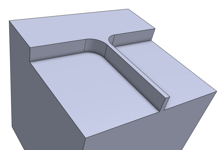
Partial Holes
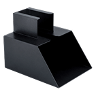
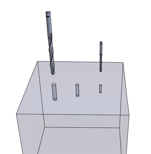
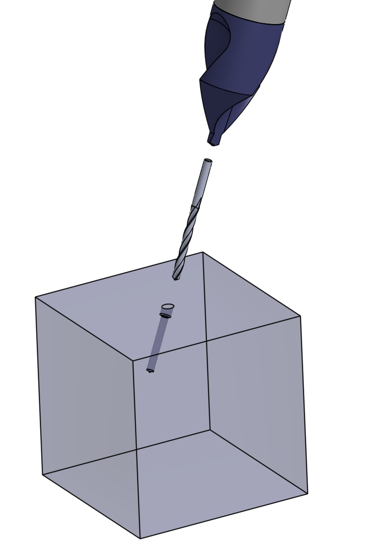
There may be times when you need to drill a partial hole that breaks out of one side, like this;
If you try to drill the hole partially outside the workpiece, you risk additional loss of accuracy and tool breakage, as the drill bit or end mill deviates towards the easier path.
Drill the hole fully, then cut away the material required to make the partial hole. This sequence of operations may involve an extra cut or tool change, but it will prevent potentially serious disruptions and errors.
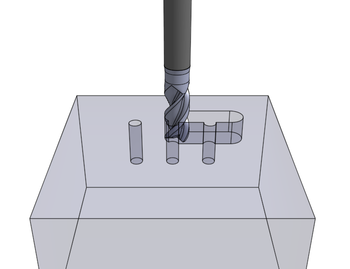
Holes Breaking Into and Through Cavities
Drilling into a cavity whose inner face is non-perpendicular to the drill or cutter can cause some considerable difficulties and loss of precision. As the drill begins to break out, it will experience side loading that will depend on the angle or curvature of the face that it is breaking out through.
The same will apply to drilling out of the other side of a cavity. This can be made worse and potentially damage the already drilled hole by chatter or side cutting, making it doubly inaccurate.
This issue is best avoided for small holes, as center drilling the cavity exit point, to maintain drill axis precision, is generally not possible. Where the drill or cutter exceeds 10mm diameter, the issue rapidly diminishes as cutter diameter/stiffness increases.

Threading Methods for Holes
hreads can be cut in three basic ways in CNC machined parts;
- Using taps (internal) and dies (external) threads can be cut inside round holes and onto posts. Minimum tap sizes are quite variable, depending on the quality of equipment. Maximum taps are essentially only limited in size by the availability of tools.
A typical minimum tap size for CNC is 3mm metric thread, ⅛” UNF. Micromachining can be used for threads of 1mm metric, but this level of finesse is to be called upon in extreme circumstances and should be avoided unless the process used is closer to watchmaking than jobbing CNC work.
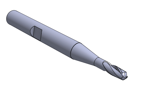
Machine taps look like this, though the can also have straight flutes, and longer threaded sections;

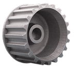
- Internal and external threads can be cut using a forming or hobbing tool that has the thread form and pitch cut on a specialist type of side cutter that looks like this:
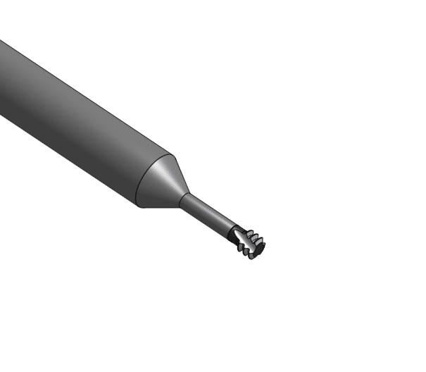
These cutters form a parallel section of thread parts as they are spun, they are traversed in a circular X-Y profile to remain in correct contact with the wall of the feature and they are traversed on the Z axis to ensure that the thread is spiral at the correct pitch.
Their advantage is the ability to produce threads of multiple diameters (with common pitch and form) using a single tool. They are also adapted to internal and external threading by exactly the same process.

- The third common technique for CNC thread cutting uses a single point cutter to traverse the entire thread form, harking back to screw cutting on a lathe. This is impractical for smaller threads, but a powerful technique where the thread cutting tool is small enough to pass into the hole.
The tool is generally fed along the hole axis in sympathy with the part rotating on the same axis. This would generally be performed using a lathe type 4th axis on a CNC machine, while the boring tool is held in the spindle to be X-Y positioned at the wall and to travel the Z axis.

Thus the tip of the tool cuts the thread profile into the bore (or external feature) in a single pass. The cutter path is shown as a helix in this view.

This type of boring bar threading can be used for holes as small as M6 metric, although it is more generally applied to holes of M16 or larger. Changing the insert allows this tool to be used on virtually any size and form of thread, including UNC, UNF, metric, Whitworth and even acme.
Thread Extent and Height
A few rules apply in threading holes, and these can inform part design and machining processes;
- In general, thread strength rises rapidly with engagement up to 3 diameters of the thread, so there is little gain in tapping to greater depths.
- The pilot holes that are threaded can be opened up to larger size. This makes lower friction threads for fasteners to engage with, as the inner peaks of the female thread are curtailed and flat-topped. Be aware, the end result of a larger pilot hole is also a weaker thread in pull-out terms.
- When CNC cutting small threads (below M6 or equivalent), allow 1-1.5 hole diameters to remain untapped, as trapped swarf risks jamming and potentially breaking the threading tool.
- When CNC cutting larger threads, spiral fluted thread cutting tools are quite effective at clearing cuttings while threading, so less unthreaded margin is required in the bottom of the hole.
There is an increasing tendency to rely on 3D files as complete information for a CNC machined part, particularly when general tolerancing and few or no specialist requirements are demanded.
Thread styles, pitches, depths etc and pilot hole diameters are hard to fully convey in 3D, as the modeling is cumbersome and easily diverges from customary specifications. On this basis, a 2D drawing must be provided at the quotation stage, to fully specify threaded elements and to avoid details being lost.
Wall Thickness
Minimum wall thicknesses require careful judgment. There are times and places where wall thickness can be pushed to extremes, if necessary.
There are also times where the rules are inflexible and must be respected. Much depends on the nature of the material;
- Many plastics suited to machining are thick slabs of material that are cast. These can have some significant internal residual stresses that will result in displacement and bending of poorly supported features.
Where the material to be cut is an injection molding, this situation can be considerably worse, as residual stresses in molded parts can be chaotic and impossible to alleviate.
This can result in unplanned cutting, as a badly supported element bends into the path of the tool.
It can also produce correctly sized features that wander from their intended position/shape.
- Some metals, especially those that have been poorly heat treated or excessively worked before machining, can display similar internal stresses and a tendency to bend when released from surrounding material.
This is less marked in metals, but can still seriously affect precision.
- Finally, even without stress induced distortion, less supported features can discover their natural frequency in the surrounding machining, allowing them to oscillate and potentially contact the cutter in the process. This is more generally referred to as chatter, when it is commonly the tool or machine structure that is oscillating, but the end result is the same.
As a rule of thumb, minimum wall thickness should be 0.8mm in metals, 1.2 to 4mm in plastics depending on the rigidity and strength. But rules of thumb are usually more exception than rule.
The guiding principle is the aspect ratios that can be evaluated. No one measurement satisfies all of the potential scenarios, so decisions about wall thickness must be driven by;
- Height: thickness aspect ratio – this defines a fundamental feature of wall thickness limitation. Tall thin features are more flexible.
- Height: length aspect ratio – longer thin features are weaker – conversely, localized support allows lower thickness without weakness.
- Material type (and condition) to thickness relationships are key. Stiffer and more rigid materials will allow thinner sections, materials with intrinsic damping will chatter less.
Thinner walls cost more. The main reason for this is that tall, thin walls greatly increase the risk of chatter, so slower feed speeds and shallower cuts are required to retain accuracy, deliver acceptable tolerances and maintain good surface finish.
The influence of material type and hardness can be complex. The natural frequency of a part, or tool, or other aspects of the machine setup can affect the ringing that results in chatter and accuracy loss. Where there is uncertainty around the risk of chatter, a more conservative approach can pay dividends. Trial cuts altering the number of cutter flutes, the spindle speed, the tool length unclamped and the support/clamping of the part can all significantly alter/reduce chatter resulting from the system offering excitation at one of the part or tool harmonics of natural frequency.
Nowhere are we going to offer you simplistic numbers to tell you which walls will work and which ones won’t. There are no clear rules and much depends on the budget you have for machining, the design imperative that drives the wall thickness, the quality of the CNC machine and cutters and the nature of the material you intend to cut.
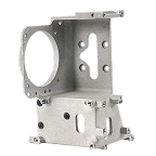
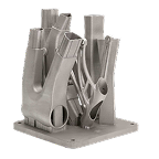
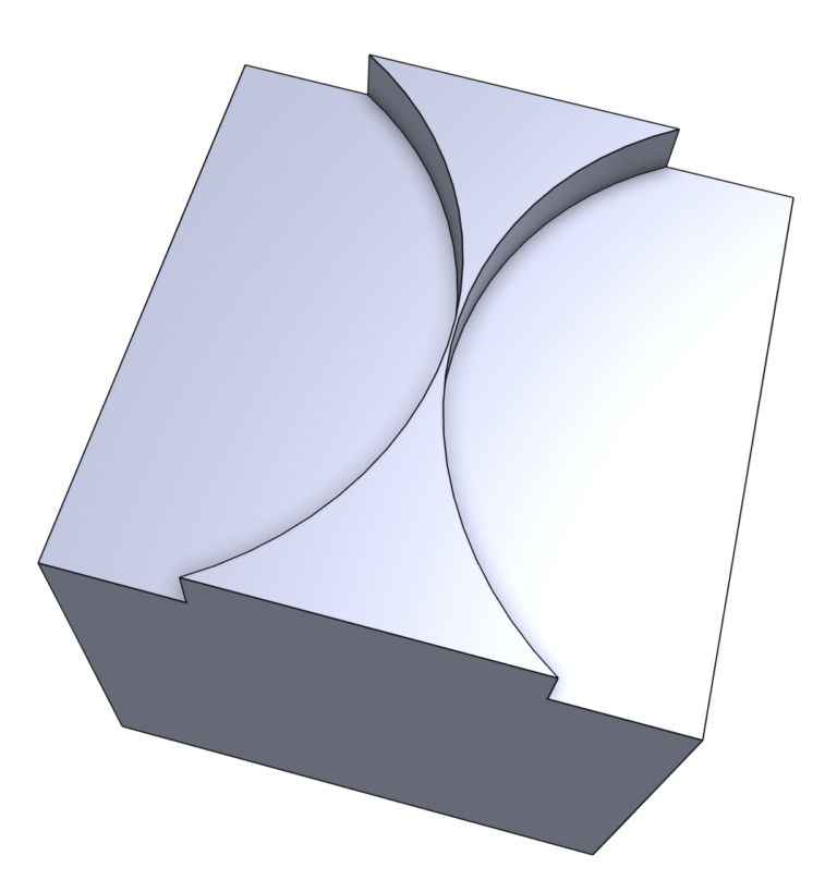
Wall Thickness #1
Where two curved features meet, you can risk bringing them very close. This feature in the model shown here is 0.4mm thick at a point, and the feature is 5mm deep.
In steel, this would cut best as one rough cut and one finishing cut for depth followed by one finishing cut on the curved surfaces for good finish and final size.
In Aluminum, you’d need 2 more finishing cuts on the curve, to avoid distorting the thin wall point. Alternatively, you could use the same cutting pattern as the steel part if you increase the thinnest point to 1mm.
How thin does the feature NEED to be? This is the key design question.
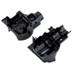
Wall Thickness #2
Where straight sided pockets come close together, the critical length to thickness to depth ratios subtly shift as feature dimensions are altered.
- Longer sections that are poorly supported will require thicker walls.
- Lower strength materials will increase the risk of element displacement. This has to be countered by increasing the wall thickness and/or reducing the depth of each cutter pass to reduce forces.
- Higher strength and higher hardness materials increase the risk of tool oscillation and chatter.
There is no guiding principle in these cases, other than it is wise to treat longer features as if the wall is unsupported (as in Wall Thickness #3).
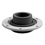
Wall Thickness #3
Where part of the wall is unsupported, there are tighter restrictions. As a general rule, a feature depth of at most 3 to 5 x the required wall thickness will be quite stable in steel or stainless steel. This assumes moderate cut thicknesses and feed rates and good quality, sharp cutters. Worsening in any of these will result in chatter and loss of precision.
In Aluminum the feature depth should really not exceed 3 x the wall thickness, although this can be improved by slower feeds, reduced cut depths and faster spindle speeds. It can also be. improved by using the higher grades of alloy, which have considerably higher strength. Age hardness or work hardening can have complex effects as stiffness affects natural frequency.
In plastics, the situation is much more variable. A soft material like LDPE is barely machinable, so sections must be much thicker – but it cuts easily and damps strongly so there’s no ringing risk in part or tool.
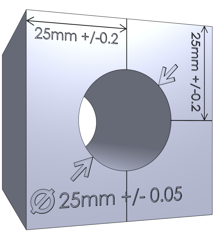
Tolerances
Tolerancing plays a critical role in design for CNC machining, to properly exploit the capabilities of the process while not adding wasteful burden to the cost of manufacture. Tolerances specify to the machinist/programmer the limits or permitted variations in the dimensions of the part.
CNC machines are capable of producing highly accurate parts within tight tolerances, but every ‘tightening’ of the dimensional variations carries a process or tooling consequence. Appropriate tolerancing means that the finished part will meet the quality and performance standards that the design implicitly and explicitly needs.
Tolerance information is hard to convey in a 3D file – attributes may allow this but the machinist/programmer can easily miss these. On that basis, where the part is not simple and/or general tolerance throughout, it is important to provide a 2D drawing with detailed annotations for these aspects, to ensure they’re fully captured at the start of pricing.
Design Intent
Tolerances are derived from the functional, assembly interaction and aesthetic demands that the design intent imparts. They communicate the necessary level of precision required for each feature to deliver on that design intent.
The decisions that result in dimensional tolerances must compromise between the function of the part, its fit with other components and the operational cost of the slower process that tighter tolerances impose.
Material Selection
Material choices significantly affect the level of tolerancing that is possible in a part. All materials are prone to dimensional changes due internal stresses, degree of rigidity/elasticity, cutting properties and localized heating due to the friction of cutting.
- Highly rigid materials such as alloy steel, stainless steel, Titanium etc suffer lower distortion due to stresses that are unevenly relieved during cutting. But they tend to have higher thermal expansion rates; they offer greater resistance to cutting and higher friction which causes heat; and they cause faster tool wear. All of these affect the ability to deliver precision and must be managed in the cutting process.
Some of the commonly machined alloys also suffer from a work related hardening process that can make cuts progressively more difficult to achieve and therefore affect tolerances. High Nickel content alloys are particularly prone to this.
- Rigid plastics suffer from much lower levels of cutter resistance and friction, so they cut cold. They also have low levels of thermal expansion, so when heating does occur its influence on tolerances and dimensional outcomes is small.
However, these materials can suffer excessive residual stress from their original casting/molding process and this can impose limitations on the manufacturing process. Given the often random nature of the residual stress in these materials, the issue is unpredictable and can be managed by stress relieving and bulk material machining to recover overall flatness.
With good handling and careful design, very high tolerances can be achieved in CNC machining of certain nylons, POM (acetal) and even PMMA (acrylic).
- Among the most machine-friendly and high tolerance capable materials are the fiber/polymer composites in the Tufnol family. These comprise phenolic resins that are reinforced with various materials (cotton, paper, glass fiber etc) to compensate for the intrinsic brittleness of the phenolic (bakelite) component.
These and similar materials are often used in engineering applications because they offer exceptional characteristics and have remarkable dimensional stability and cutting properties in CNC processing.
They can deliver the highest tolerances in machining, without the excessive cost related to super fine-cut machining.
Machine Capabilities
The quality, condition and capability of the CNC machine being used can impact the achievable tolerances. High-precision machines with advanced features can produce parts with tighter tolerances than less advanced machines.
One of the biggest influences is the need to reset the workpiece to a different orientation, with an inevitable loss of precision resulting from the need to renew the machine datum, which is a moderately error prone process.
The highest tolerances require a single setup, or regional tolerancing that is closer than the inter-feature tolerances that can be maintained. Where high precision is required from all orientations/cutter presentations of the work, a more advanced, multi axis machine that can retain the part in a fixed arrangement that allows it to be reorientated without a reset of datum will deliver higher precision.
Design that constrains the use of more expensive equipment, to deliver tolerances that might have been more relaxed, should be avoided.
Tooling and Tool Wear
Tool cutting edge wear and tool deflection heavily influence tight tolerances by creating some degree of uncertainty as to where the cutting edges are.
- Degraded cutters can erode away to reduce the cut depth marginally. They can also fracture and spall unevenly, rendering surfaces less flat. Tis latter can be countered by diversity in finishing cust, so no one region of the cut surface relies solely on one narrow zone of the cutting faces.
Of course that diversity requires additional tooling passes, which raises costs by reducing productivity.
Close monitoring and maintenance of tooling is essential to ensure consistent tolerances across production runs – and the highest tolerances are generally best achieved with new cutters.
- Deeper cuts can place higher side forces onto cutters, causing them to flex away from the cut. This can be counteracted by a combination of shallower cuts and slower feed rates. The more times a region of the component faces cutting edges in any given tool-pass, the more closely the resulting face will reflect the precision of the tool and the machine.
But slower cutting drives up production costs, so the relaxation of tolerances, where not disruptive of function or quality, directly affects manufacturing cost/productivity.
Inspection and Quality Control:
Tighter tolerances usually require more extensive inspection and QA procedures to validate adherence to specification in the part. This may involve the use of coordinate measuring machines (CMMs) and other precision measurement tools, all of which require CAPEX and skilled labor to operate.
General tolerancing is usually able to be validated at the machine, either during processing pauses or at unloading. This level of QA is essentially cost-free, as it is part of basic machine operation.
For large scale production, the use of go-no-go gauges that are manufactured to allow rapid inspection/validation of limits and fits can allow fast processing for moderately high tolerances, although these specialist tools cost money and require careful handling.
In some industries, such as aerospace and medical manufacturing, there are strict regulatory standards that dictate tolerances for safety and performance reasons. Adhering to these standards is crucial in delivering CNC machining outcomes that are as-required and reliable.
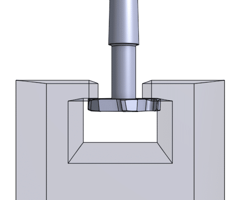
Undercuts
Undercuts for slide, keyways or facilitating simplified openings to complex cavities can be achieved with dovetail and T-slot cutters. These devices are of restricted capacity but can be very empowering in enabling design complexities that have little of no bearing on component production costs.
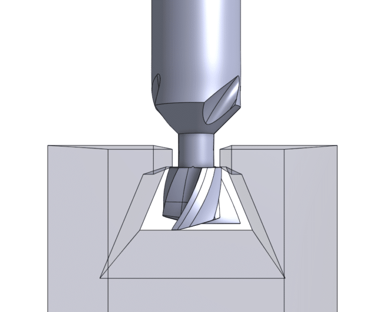
In many cases, open channel (as opposed to subterranean) undercut features can be achieved with more basic tooling, but the part orientations required to deliver this will drive use of 4 axis equipment (at higher machining cost) or component resets (with both time cost and precision loss).
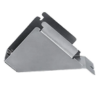
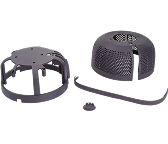
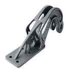
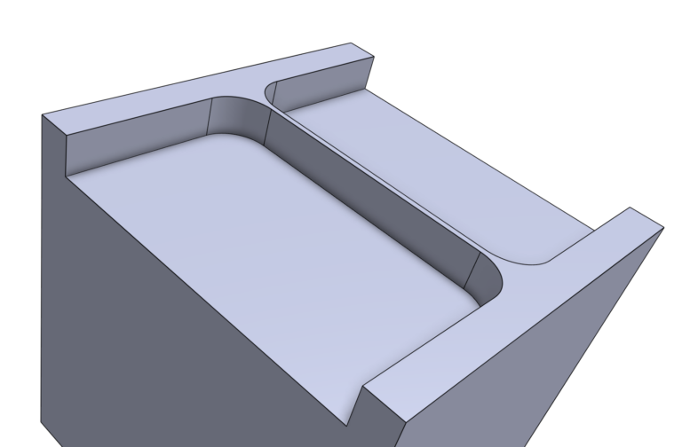
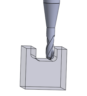
Radius Junctions Points
Where possible, avoid sharp transitions between features. These increase stress concentration and reduce tool life by requiring absolute corners on cutters. Typically this is achieved by use of ball-ended cutters such as that shown in a cut off detail here;
The end result is features that blend into each other, avoiding sharp transitions where it is practical to do so;
Component Clamping/Retention
How a part is retained in a CNC machining process doesn’t, on the surface, look like a design issue. In reality, the type of clamping available depends heavily on the nature of the available equipment and with complex parts, this can have a significant impact on manufacturing costs. It can be unavoidable to design with a machine clamping arrangement in mind, if accidental component cost-up outcomes are to be avoided in machine type step-ups or custom clamping tools.
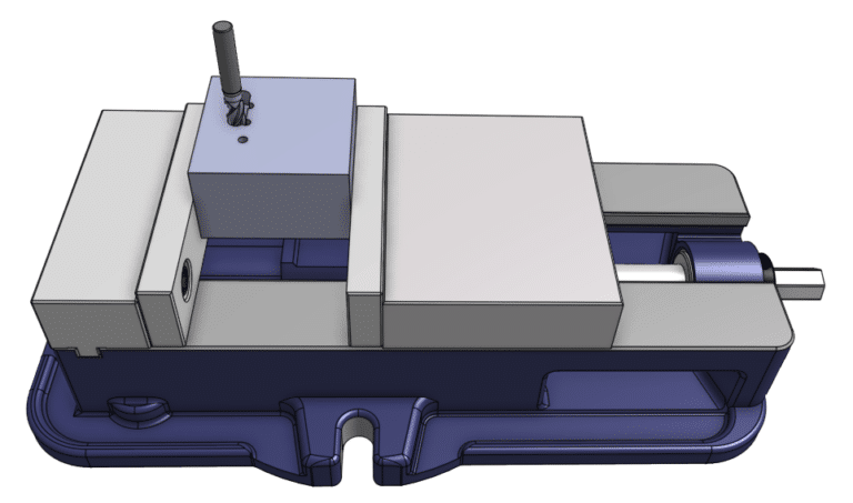
- Parts that can be entirely machined from one face can be held in a standard machining vice and will only have to be positioned and machine datum validated once.
This approach works well for one off parts but it is poorly adapted to production runs, as the machine datum must be recreated for every part. A fixed position can be achieved by making secondary vise-jaws that include a precise position for the parts to be repeatably retained in, reducing the risk in placement.
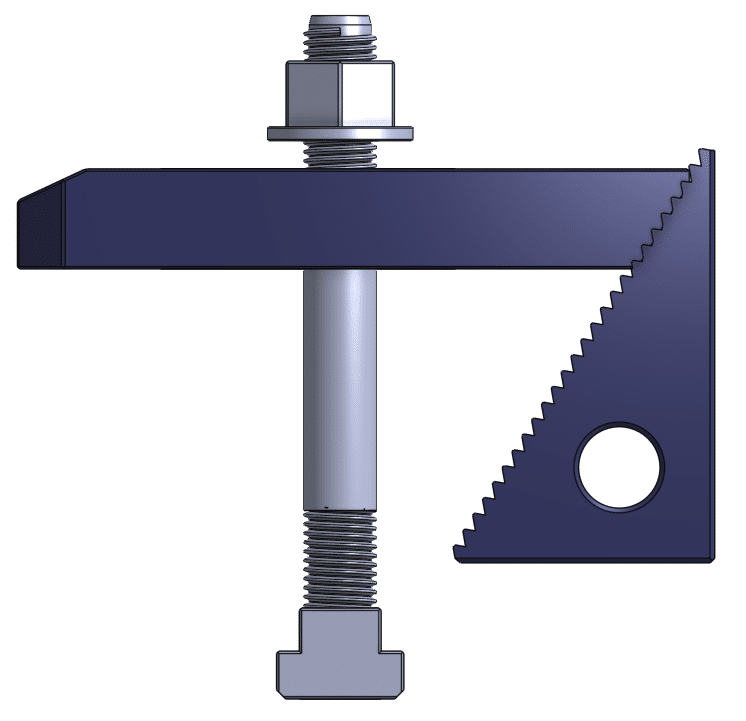
- More complex (one off) parts that require greater cutter access and are to be produced on typical 3 axis CNC equipment can be T-slot clamped using standard clamping tools that are typical in all machine shop equipment.
- Where increased access and an increased number of axes are available (4 or 5 axis CNC or better), then more appropriate camping mechanisms are available that allow the machine to present the work to the cutter in more orientations.
Conclusion
The cost implications of ealy design choices can be significant. It is critically important for the initial design effort to bear in mind any aspects of the mass production that can be foreseen – and that foresight is the key to effective design.
Follow simple rules:
- Use the largest diameter cutter that can be applied to the task.
- Consider stress relief in element junctions
- Use thicker walls where possible
- Use the lowest tolerances that can deliver function