
A successful prototype answers: does the design work? Production manufacturing answers: can it be manufactured, repeatedly?
Many projects fail in the gap between those milestones. Components that perform when prototyped often require redesign for injection molding. The problems rarely involve design flaws, they emerge as tolerance and molding issues drive tooling modifications.
Moving from 3D printed prototypes to production injection molding solves different problems. Additive manufacturing accelerates design validation, while injection molding delivers repeatable quality at the lowest practical unit cost. A successful transition requires understanding how geometry, materials, tooling and manufacturing processes interact long before the mold is ordered.
Why the 3D-to-injection molding transition breaks down
One of additive manufacturing’s strengths is freedom from conventional manufacturing constraints. Internal channels, undercuts, lattice structures and highly variable wall sections can be printed without challenge.
Injection molding works differently.
Molten polymer must fill the cavity consistently, cool at a controlled rate and release cleanly from the mold, and this must repeat thousands, or even millions of times.
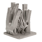
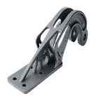
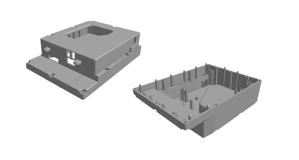
This illustrates how successful prototypes become difficult production parts.
Features that often require redesign
These geometries frequently trigger DFM changes before tooling.
| Geometry | Prints Easily | Typical Molding Challenge |
|---|---|---|
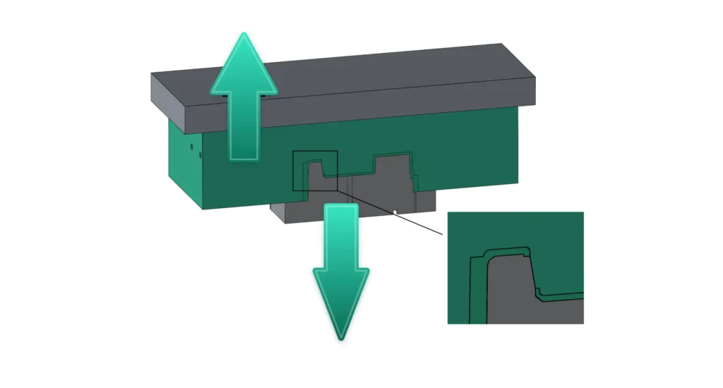
| Deep undercuts | Yes | Requires side actions or lifters |
| Internal cavities | Yes | Difficult without inserts or collapsible cores |
| Variable wall thickness | Yes | Sink marks, differential cooling and warpage |
| 4th dimension engagements | Sometimes | Often impossible without tooling undercuts and T0-TX adjustments |
| Sharp internal corners | Yes | Poor material flow and stress concentration |
| Thin knife edges | Sometimes | Difficult cavity filling and premature wear |
They are untoolable or increase tooling complexity, manufacturing cost, or process variation. Identifying them during DFM review is far less expensive than modifying hardened tooling after machining.
Tolerances change more than most engineers expect
A common mistake is assuming that dimensions proven on printed prototypes will perform during production.
Typical best-case dimensional capability illustrates why that is risky.
| Manufacturing Process | Typical Closest Tolerance |
|---|---|
| FDM | ±0.50 mm |
| SLS | ±0.30 mm |
| MJF | ±0.20 mm |
| Production Injection Molding | ±0.05–0.13 mm |
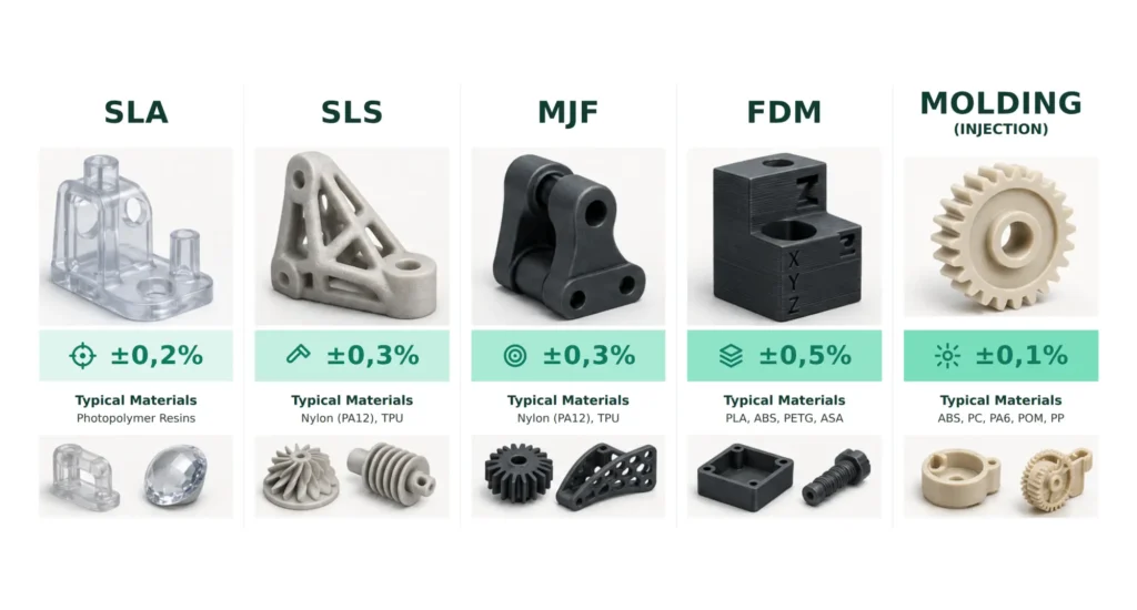
Injection molding offers substantially tighter dimensional control. Tightened tolerances can change assembly behaviour.
- Clearance holes become interference fits.
- Snap features require more force.
- Living hinges require tuning.
- Fastener behaviors change.
Changes require assemblies to be revalidated, and tools to be modified. A tolerance stack analysis should use expected molded dimensions, rather than trusting prototypes. ISO 20457 guides molded-part tolerancing, throughout development.
This requires a careful caveat. Injection molding precision depends heavily on material, additives, geometry, dimension length, gate location, packing, tool wear, moisture content, and processing. Typically very few areas require or achieve ±0.05 mm. This can be achieved in localized regions, whereas tight tolerances over longer measurements are both less achievable and typically not necessary.
The most expensive mistake happens before tooling exists
Many projects attribute production delays to tooling.
In reality, the root cause is often timing.
Engineering validates prototypes, then procurement issues tooling RFQs.
Only then does the mold designer undertake DFM. This exposes problems in draft, gate placement, steel thickness, cooling imbalances, or ejection. Every issue forces redesign, delays tooling and increases costs.
A collaborative engineering review before the tool is quoted ALWAYS costs less than correcting steel after it is cut.
Redesigning for moldability without losing design intent
DFM doesn’t alter what a product does. It changes details to ease manufacture, preserving design intent.
The objective is translation of a validated prototype into a repeatable manufactured outcome.
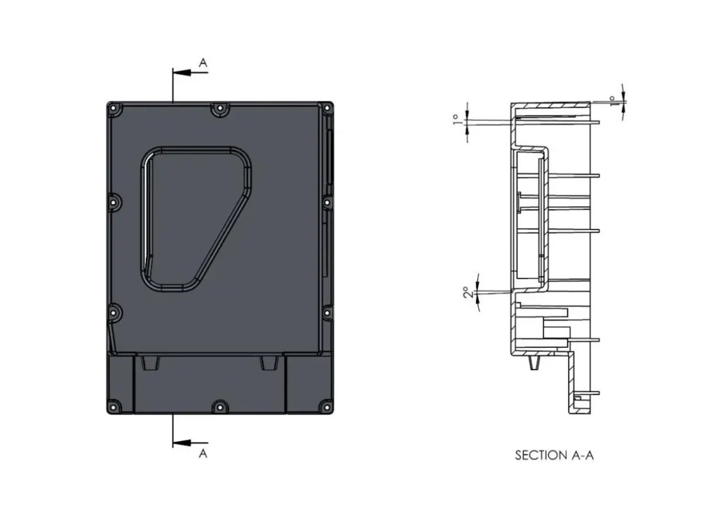
Design draft into every vertical surface
Draft is key to ejection.
With insufficient draft, molded parts hang-up, increasing ejection force, and suffer scuffing and distortion.
General recommendations include:
| Surface | Recommended Draft |
|---|---|
| Smooth polished surfaces | 1° minimum |
| Light texture | 1.5–2° |
| Heavy texture | 2–3° minimum |
Typical DFM guidance adds at least 1° and up to 1.5°of draft for every 0.025 mm of texture depth to avoid drag marking by releasing the texture features undamaged, but this is a deceptive generalization.
The range is appropriate for photoetched, smooth bump textures (approximating leather texture or ‘spatter’ finishes).
For surfaces with sharper texture micro features such as those from grit blasting, a rate of at least 1.5° and commonly greater per 0.025mm is more appropriate \- and rates of 2 and 3° are not unusual for crisp logos to release without damage.
Deeper parts and highly filled polymers require additional draft, due to increased ejection friction.
Uniform wall thickness controls quality
Wall thickness influences every aspect of injection molding.
Large thickness variations create uneven cooling, resulting in residual stress, sinking, and warping. Thick sections increase cycle time, as cooling/solidification becomes extended.
Accepted design practice recommends:
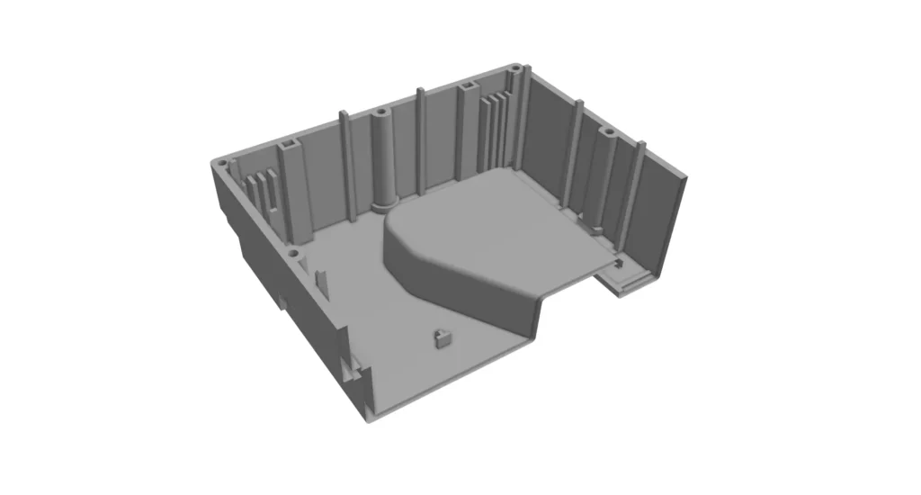
- Rib thickness of max 60% of attached wall thickness.
- Rib height max three times wall thickness.
- Fillet where ribs intersect walls.
These proportions improve stiffness, and maintain cosmetic quality and dimensional stability.
Gate location should be an engineering decision
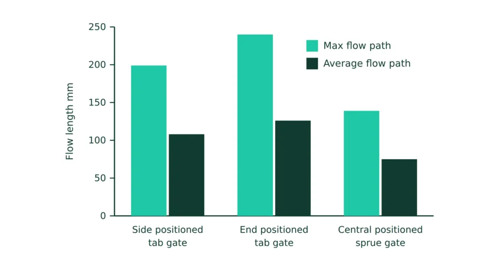
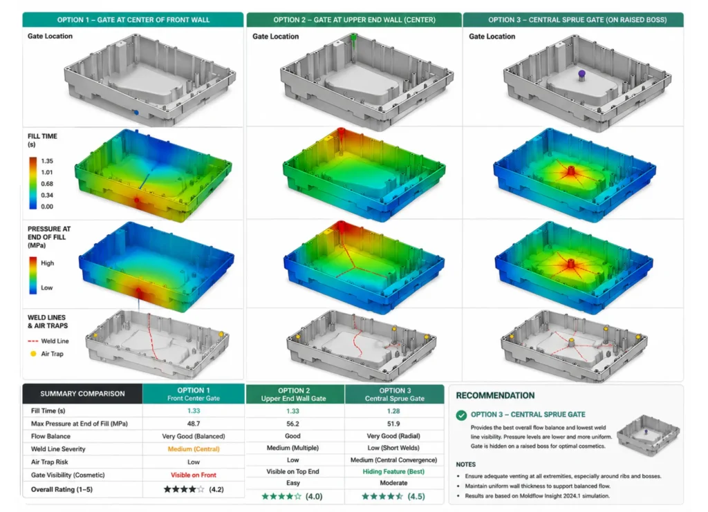
Gate position influences more than filling, driving:
- weld-line location
- fibre orientation
- shrinkage behaviour
- cosmetic appearance
- and mechanical strength.
The best approach is to define cosmetic surfaces and critical functional areas before tooling begins. The mold designer will optimise gate location around engineering priorities.
Some printed features become tooling features
One of the biggest conceptual shifts during 3d printing to injection molding is recognising that not every feature belongs in the part geometry.
Some become tooling mechanisms instead.
Examples include:
- Side actions
- Lifters
- Unscrewing cores
- Collapsible cores
- Replaceable inserts
- These mechanisms increase tooling cost, the trade-off being reduced labor in assembly.
- These choices are driven by production volume, product life, and tooling budget.
Bridge tooling injection molding: Reducing commercial risk
One of the most common assumptions in product development is that a validated prototype justifies molding.
That is not the case.
Many prototypes occupy an intermediate phase, where production forecasts remain uncertain. Sales volumes may be developing, certification may be incomplete, or customers may request final design refinements.
In these situations, bridge tooling injection molding offers a way to reduce both technical and commercial risk. Engineers use Aluminum tooling to manufacture production-quality components, while validating manufacture, demand, and design stability.
The result is lower overall project risk.
Understanding the three tooling stages
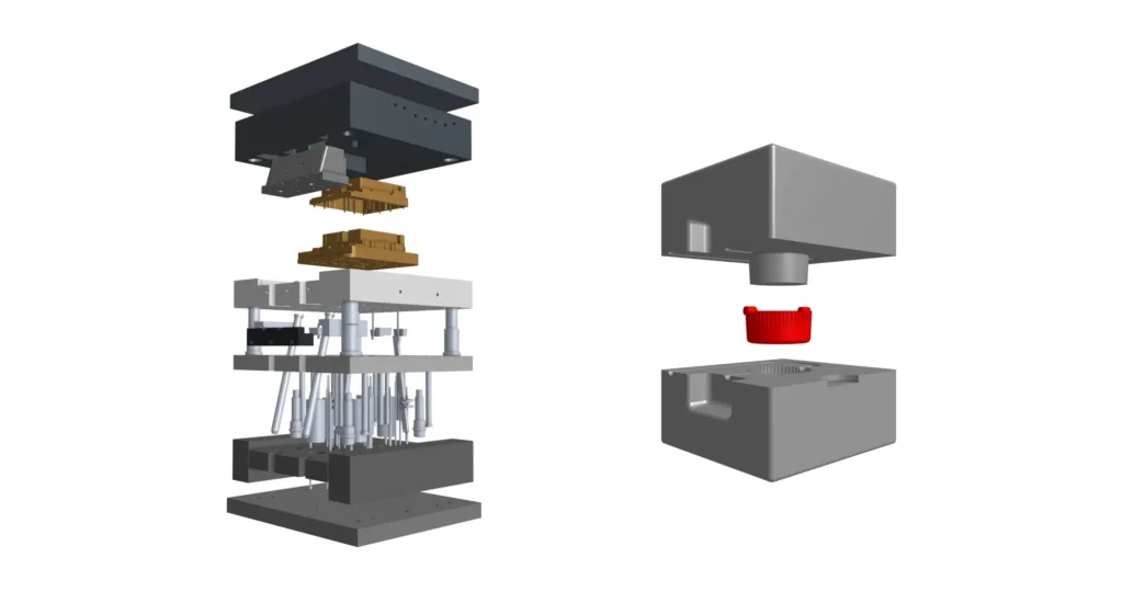
Not every injection mold is designed for the same objective. Prototype tooling, bridge tooling, and hardened production tooling occupy different points on the product development lifecycle. Selecting the wrong option can either increase unnecessary CAPEX, or create avoidable production constraints.
| Tool Type | Typical Cost | Tool Life | Lead Time | Best Application |
|---|---|---|---|---|
| Prototype aluminum tooling | US$2,000 to 8,000 | 500 to 10,000 shots | 2 to 4 weeks | Product validation, pilot production |
| P20 production tooling | US$15,000 to 80,000+ | 100,000 to 500,000+ shots | 6 to 12 weeks | General production |
| H13 hardened steel tooling | US$40,000 to 150,000+ | 500,000 to 1,000,000+ shots | 8 to 16 weeks | High-volume production, abrasive engineering resins |
These figures vary considerably with part size, cavity count, surface finish, cooling complexity, and polymer selection, but the scale guides planning.
Durability performance depends on many variables. A P20 tool running acetal (POM) for example, is likely to see surface degradation at 10 to 20k shots (hence the use of stainless steel cavity plates and ejection pins in POM tools, to counteract the acidity of the molten charge).
The same P20 tool running a mild character resin such as polypropylene (PP) might easily exceed 500k shots.
In a similar vein, Aluminium tool life is EXTREMELY variable with part complexity, material, additives, and processing conditions. A side movement and blanking feature such as that in the enclosure component discussed in this article severely limits total tool life – with high confidence of hundreds of shots, but maintenance likely to be required before 2000 shots.
A simple, open and shut Aluminium tool such as that shown in Fig X (\#\#\#\#\#\#\#\#) running PP or PE might well serve for 5 to 10 thousand shots with little maintenance.
When aluminum tooling makes sense
Well engineered Aluminum (soft) tooling routinely produces thousands of production-quality parts, while offering considerably shorter lead time and cost, compared with mass production molds.
For many products, Aluminum tooling is the logical next step after successful prototyping.
Typical applications include:
- Pilot production
- Clinical or regulatory trials
- Market validation
- Bridge production
- Spare parts
- Low-volume industrial equipment
- Early customer deliveries
Design modifications can often be implemented quickly and at low cost. For products that are still evolving, this agility can be immensely valuable.
When steel tooling becomes the better investment
Eventually, production volume drives revised economics.
Hard steel tooling becomes the right solution when:
- annual demand exceeds a few thousand components
- production is expected to continue long-term
- multi-cavity molds are justified
- engineering polymers with glass, mineral fillers, or flame retardants are specified
- dimensional rigor is required through long production runs
- cycle time optimisation offers commercial benefit
Although the cost is substantially higher, the lower maintenance requirements, longer service life and improved productivity usually deliver the lowest total manufacturing cost over larger volumes.
Understanding the cost crossover
Opting between Aluminum and steel tooling shouldn’t be based on tool price, but comparison of manufacturing cost across the anticipated product lifecycle.
Consider a relatively simple example.
Aluminum tooling costs US$6,000.
Comparable steel tooling costs US$30,000.
The aluminum option appears cost-attractive.
However, at an annual demand of 20,000 units, the Aluminum tool may require replacement after a few months. Cycle times will be longer, cavity count lower and part cost elevated.
The steel tool, despite its higher apparent cost, often becomes the less expensive option because it provides:
- faster production cycles
- lower maintenance costs
- greater dimensional repeatability
- improved process stability
- reduced downtime
- lower scrap rates
Evaluating tooling as a capital asset rather than a purchasing decision usually produces better long-term outcomes.
Bridge tooling injection molding is about process validation
Perhaps the greatest benefit of bridge tooling injection molding is not the production of parts.
It is the creation of manufacturing knowledge. Bridge tooling allows engineers to optimise:
- injection pressure
- packing pressure
- holding pressure
- melt temperature
- mold temperature
- cooling time
- gate freeze time
- ejection strategy
- cycle time
By the time hardened production tooling is commissioned, the processing window will be well established. Instead of beginning process development with T1 samples, engineers can concentrate on fine-tuning an already validated manufacturing process.
This frequently shortens production launch schedules, despite double tooling, while greatly reducing technical risk.
When bridge tooling injection molding is not appropriate
Despite its advantages, bridge tooling is not suitable for every case.
Direct investment in hardened tooling is generally appropriate when manufacturing:
- glass-filled engineering polymers
- PPS, PEEK or other high-temperature thermoplastics
- Acetal (POM) and acidic polymers
- Class A cosmetic components
- extremely tight tolerance parts
- products expected to exceed several hundred thousand units
- high-cavity molds where productivity is the primary objective
In these situations, the additional durability of hardened tooling generally offsets the higher purchase cost.
Managing the supplier relationship across the transition
Many production delays originate from communication, rather than manufacturing issues.
It is common for prototypes to be sourced from one supplier before production tooling is awarded elsewhere. While commercially attractive, this approach will always interrupt the transfer of engineering knowledge to some degree.
The prototype supplier understands why features exist.
The mold maker often receives only CAD geometry.
Prototypes sourced through the selected tooling/molding supplier can a) improve the DFM and transition processes and b) slow down the prototyping as more hands get involved.
Engineering should participate in DFM discussions
Procurement teams play an essential commercial role, but mold designers also need direct engineering input.
Important questions include:
- Which surfaces are cosmetic?
- Which dimensions are functionally critical?
- Which tolerances are negotiable?
- Which features cannot change?
- Which ribs or bosses carry structural loads?
Answering these questions before tooling begins allows the mold designer to optimise around engineering intent, rather than making assumptions from geometry alone.
Material selection should be revalidated
A printed prototype rarely uses the same material as the production component.
SLS prototypes commonly use PA12.
Production parts may instead specify:
| Molded Polymer | Typical Shrinkage |
|---|---|
| Nylon PA6 | 0.7%–2.2% |
| Nylon PA66 | 1.0%–2.0% |
| Nylon PA6 GF30 | 0.2%–0.8% |
| ABS | 0.4%–0.8% |
| PBT | 1.2%–2.0% |
| PC/ABS | 0.4%–0.7% |
| POM | 1.5%–2.5% |
These materials differ substantially in shrinkage, moisture absorption, stiffness and impact resistance. See Jiga’s engineering plastics material guide for a detailed comparison.
Prototype to production injection molding checklist
Before releasing tooling, confirm:
- Production resin selected
- Complete DFM review completed
- Tolerance stack verified
- Draft angles confirmed
- Rib and boss geometry reviewed
- Tooling strategy selected
- Gate location approved
- Shrinkage assumptions validated
- Inspection plan established
- T1 sample review scheduled
- CAD revision frozen
Following this sequence prevents many of the avoidable delays that can occur.
Notes on boss geomtery
Generic rules for boss geometry are widely cited. A simple version of this is that a boss O/D must be at least 2 x the I/D.
This generic advisory lacks specificity.
Two forms of boss are common. Solid bosses have no I/D, where cored bosses have a hole in the center.
All bosses attach to a wall, and typically they are outer-face drafted at 1°. The diameter of a solid boss at the wall must not exceed 60% of the attached wall thickness, to avoid sink marks on the obverse face.
A cored boss requires a more complex definition. The typical restriction is that the thickness of the annular wall of the boss must not exceed 60% of the attached wall, where they meet, to avoid sink marks.
However, the core pin that forms the central hole in such a boss is typically parallel. This induces severe drag at ejection and will cause sticking.
To solve this, the boss is most often formed using a sleeve ejector that applies ejection load around the core pin, removing it cleanly. To facilitate this, the core pins must not only be mirror finish, but also DRAW POLISHED to minimise the large ejection forces.
The end result of this complexity renders generic boss-geometry guides as largely uninformative.
The boss must comply with the 60% rule at the wall, be drafted sufficiently to eject, and have sufficient annular wall at the tip to allow sleeve ejection of the core pin to work without crushing the boss tip. The final aspect of this will vary considerably with material toughness and rigidity.
Additionally, the intended use of the boss influences the geometry. If the boss center hole is to be used as a threaded fixing receptacle, the boss must have sufficient wall section (from the tip to the screw engagement depth) to resist the annular load imposed by the fastener. This is highly dependent on fastener type, thread engagement and the polymer being molded.
Successful prototype to production injection molding projects typically reference:
| Standard | Purpose |
|---|---|
| ISO 20457 | General tolerances for molded plastic parts |
| ISO 294 | Injection molding test specimens |
| SPI Mold Finish Standards | Surface finish classification |
| ASTM D638 | Tensile properties |
| ASTM D790 | Flexural properties |
| ASTM D256 | Impact testing |
| ASTM D648 | Heat deflection temperature |
These standards provide a common engineering language for all contributors.
Key takeaways
The transition from 3D printed prototypes, to prototype injection molding, to production injection molding is fundamentally an engineering exercise rather than a purchasing decision. It’s critical to recognise that prototyping validates design intent, while molding validates manufacturability.
Projects that reach production on schedule share several characteristics. They:
- complete DFM before tooling is quoted
- redesign geometry for moldability without compromising function
- validate production materials rather than assuming prototype behaviour will transfer directly
- select a tooling strategy that reflects realistic production volumes
- Most importantly, they maintain communication between the designer, molder, and the production team. When engineering intent is clearly understood before steel is cut, tooling modifications become the exception rather than the rule.
The result you will see, with Jiga’s custom manufacturing platform, is faster production launch, lower lifetime manufacturing cost and a smoother transition from prototype to mass production. Whether your project begins with 3D printing, progresses through CNC machining for bridge production, or moves directly into production injection molding, early engineering, collaboration, DFM and Jiga support remain the keys to successful manufacturing.
Frequently Asked Questions
Can I move directly from 3D printed prototypes to production tooling?
Yes, provided the design, production material and expected manufacturing volume are stable. If significant design changes remain likely, bridge tooling injection molding generally reduces both technical and financial risk.
What is bridge tooling injection molding?
It uses aluminum production tooling to manufacture production-quality components while validating tooling, processing parameters and market demand before investing in hardened steel molds.
Can I use the same material I printed?
Sometimes, but rarely without validation. Production materials often differ substantially in shrinkage, stiffness, weld-line strength and moisture absorption, requiring the design to be reviewed before tooling begins.
When should I invest in hardened steel tooling?
Steel tooling generally becomes the better investment once production exceeds a threshold that allows effective amortisation; or when abrasive engineering polymers, high-cavity molds or very long production runs are expected; or when demand rises to the level that multi-cavity tooling is a necessary step.
What is the biggest cause of production delays?
The most common cause is delaying DFM until after tooling quotations are requested. Early collaboration between engineers and mold designers usually prevents costly redesign and tooling modifications.