
5-axis CNC machining involves a rotating cutter traversing five independent axes, generally simultaneously, to machine complex geometries with high precision.
- A traditional 3-axis machining moves the part (or cutter, or a combination of the two) linearly along X, Y, and Z.
- A 5-axis machining adds two perpendicular-axis rotational movements, allowing the tool to approach from virtually any orientation.
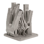
For the more complex features that this facility enables, the multiple axes must be operated in concert, to allow smooth transitions between and across curved surfaces. This enables the production of intricate parts with undercuts, compound angles, and multi-surfaced features in a single setup.
Key takeaways
- 5 axis CNC machining unleashes the potential of metal cutting to extract complex and intricate forms from the solid.
- The increased sensitivity of the tool/material interface equips a paradigm shift in quality of outcome.
- The increased efficiency of the cut distributes tool wear and process stress, improving equipment durability and performance.
- The skills required are more intricate and involve deeper knowledge of process and materials, to deliver excellence.
Understanding the five axes of movement
Linear axes (X, Y, Z) are the fundamental axes in any CNC machine, defining straight-line movements along Cartesian coordinates.
- X-Axis: Moves the tool (or workpiece, depending on machine configuration) laterally
- Y-Axis: Moves the tool or table in the depth direction.
- Z-Axis: Raises or lowers the tool (or table) along the vertical axis, for depth of cut, drilling, and pocketing.
The X, Y, and Z axes form the cartesian coordinate system, defining the 3D linear workspace of the machine. All movements along these axes are strictly translational.
Rotational Axes (A, B): Rotational axes allow the tool or the workpiece to pivot, enabling machining on multiple faces without re-fixturing.
- A-Axis: Tilts the tool or workpiece forward and backward.
- B-Axis: Tilts the tool or workpiece side to side.
- Optional C-Axis: Some machines include a C-axis (rotation around Z). The extra rotational axes allow the cutting tool to approach the workpiece from virtually any angle.
They enable simultaneous 5-axis machining, which allows:
- Continuous tilting of the tool along a curved path.
- Reduced tool interference.
- Better surface finish on complex geometries like turbine blades or molds.
| Feature | 3-Axis Machining | 5-Axis Machining |
|---|---|---|
| Movement | Linear along X, Y, Z only | Linear (X, Y, Z) + Rotational (A, B) |
| Complexity | Limited to prismatic, planar, and simple contoured parts | Handles complex surfaces, undercuts, and multi-faceted geometries |
| Setup | Often requires multiple fixtures and repositioning | Single setup often sufficient for complex parts |
| Tool Access | Tool approaches from a fixed vertical orientation | Approach from multiple angles; reduced collisions & better reach |
| Applications | Simple parts, flat surfaces, pockets | Aerospace components, medical implants, turbine blades, molds |
How 5-axis differs from 3-axis and 4-axis systems
3-axis machining centers have axes: X, Y, Z (linear) only.
- The tool remains perpendicular to the XY plane, so it can only cut vertical or flat surfaces relative to the Z-axis.
Part must often be reoriented manually to machine multiple faces.
Advantages; Simpler, less expensive machines. Easier programming and operation for prismatic parts.
Limitations; Cannot easily machine complex 3D surfaces, undercuts, or angled features. Requires multiple setups.
5-axis machining centers; Axes: X, Y, Z (linear) + A AND B (rotational)
- Tool can tilt and rotate simultaneously, providing virtually unrestricted access to the part.
Allows true 3D contouring of complex geometries in a single setup.
Ideal for aerospace, medical implants, turbine blades, molds, and dies.
Advantages over 3- and 4-axis; Fewer setups allows for reduced error-risk accumulation and typically much higher precision. Complex surfaces and undercuts can be machined without special fixtures. Better tool orientation results in improved surface finish and tool life.
Limitations; Higher cost of equipment and processing, and more complex programming. Requires skilled operators and sophisticated CAM software.
| Feature | 3-Axis | 4-Axis | 5-Axis |
|---|---|---|---|
| Linear axes | X, Y, Z | X, Y, Z | X, Y, Z |
| Rotational axes | 0 | 1 | 2 |
| Tool approach flexibility | Limited | Moderate (rotation around one axis) | High (multi-angle access) |
| Multi-sided machining | Multiple setups | Single setup for some features | Single setup for complex parts |
| Suitable parts | Simple prismatic | Cylindrical, some angled | Freeform surfaces, undercuts, complex 3D |
| Programming complexity | Low | Medium | High |
What are the different Types of 5-axis CNC machines
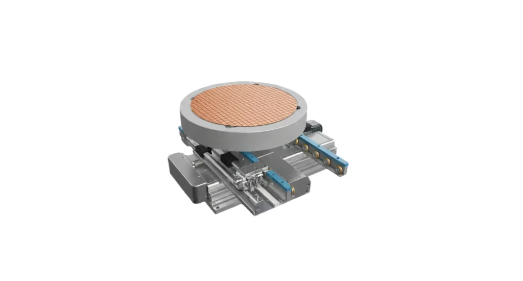
Swivel-table (or trunnion-style) 5-axis machining center
The workpiece is mounted on a rotating and tilting table (trunnion).
Linear axes: X, Y, Z (usually moving the spindle), rotational axes: A and B (rotations are applied to the table, not the spindle).
| Parameter | Typical Values |
|---|---|
| Table rotation (B-axis) | ±110° to ±120° tilt |
| Table swivel (A-axis) | ±360° or continuous rotation |
| Linear travel (X/Y/Z) | 500–2000 mm |
| Spindle speed | 8,000–20,000 RPM |
| Load capacity | 500–5,000 kg depending on table size |
This type of machine is typically suited to steadier machining of larger and heavier workpieces – engine blocks, turbine housings, rocket nozzles etc.
Limitations of the type are: tool approach angles limited by table geometry and they require more complex CAM collision avoidance.
Head-Table (or Swivel-Head) 5-Axis Machining Centers
The workpiece is usually fixed; the spindle head itself rotates and tilts. Additional axes of motion come rotational axes A and B in the spindle head (tool center swivels instead of the workpiece).
| Parameter | Typical Values |
|---|---|
| Spindle tilt (A-axis) | ±110° to ±120° tilt |
| Spindle swivel (B-axis) | ±360° or continuous rotation |
| Linear travel (X/Y/Z) | 300–1000 mm (smaller than table-table) |
| Spindle speed | 12,000–50,000 RPM (high-speed machining possible) |
| Workpiece load | Up to 500–1,000 kg (smaller than trunnion style) |
This type is best suited to complex contours and high-precision work, with smaller/lighter footprint.
These machines are typically limited to lighter parts and offer somewhat less rigidity than table-table for heavy cutting.
| Feature | Table-Table (Trunnion) | Head-Table (Swivel-Head) |
|---|---|---|
| Rotational axes | Table moves (A & B) | Spindle moves (A & B) |
| Best for | Heavy, large parts | Small, high-precision parts |
| Linear travel | Larger (500–2000 mm) | Smaller (300–1000 mm) |
| Spindle speed | Moderate (8k–20k RPM) | High (12k–50k RPM) |
| Workpiece weight | High (500–5,000 kg) | Moderate (up to 1,000 kg) |
| Applications | Aerospace engine casings, molds | Medical, turbine blades, electronics molds |
Indexed 5-axis machines
Indexed 5-axis machines are a subset of 5-axis CNC machining centers, but they operate differently from simultaneous 5-axis machines.
An indexed 5-axis machine (also referred to as a positional 5-axis system) has A, B rotational – but the rotational axes only move to discrete positions (“index”).
| Feature | Indexed 5-Axis | Simultaneous 5-Axis |
|---|---|---|
| Rotational axis motion | Moves only between cuts (positioned) | Moves continuously during cutting |
| Tool path complexity | Limited | Can follow true 3D complex surfaces |
| Programming | Easier | More complex CAM required |
| Collision avoidance | Easier to manage | Must carefully control all axes |
| Applications | Multi-sided machining, angled drilling | Freeform surfaces, aerospace turbine blades, molds |
This approach offers simpler programming and control than full simultaneous 5-axis, and lower cost equipment than continuous 5-axis machines.
However, they cannot produce complex 3D contoured surfaces in a single pass, as the tool cannot tilt dynamically during cutting.
They typically serve in;
- Drilling, tapping, or milling angled holes.
- Machining prismatic parts that require multiple angled operations such as automotive engine blocks.
- Fixtures and jigs that benefit from multi-sided machining in one setup.
Simultaneous (continuous) 5-axis machines
Simultaneous 5-axis machines can move all five axes (X, Y, Z, and A plus B or C) at the same time during cutting. This allows the tool tip to maintain a precise, dynamic orientation relative to the workpiece surface, enabling true freeform surface machining.
CAM software generates a 5-axis toolpath that defines both tool position and orientation at every step. This is ideal for compound curvature and complex profile parts.
These systems can offer;
- Complex geometry machining of sculpted, organic, or freeform shapes in one setup.
- Reduced setups, undercuts, and deep cavities without re-clamping.
- Improved surface finish.
- Longer tool life due to reduced side loading.
- Higher precision.
However, this type of equipment entails;
- High cost machines, CAM software, and controllers.
- Elevated programming complexity.
- Greater collision risk, requiring simulation.
- Higher maintenance.
This class of equipment is most commonly reserved for higher value components using higher spec materials.
What are the Key advantages of 5-axis CNC machining
The key advantages of 5-axis CNC machining include the ability to process complex shapes in a single setup, which improves accuracy and reduces lead times. This method minimizes tool vibration by using shorter cutting tools, resulting in superior surface finishes and extended tool life across intricate geometries.
In 3-axis machining, each angled face typically requires a new fixture setup. Every re-clamp introduces positional error due to fixture tolerance and operator alignment.
The most quantifiable benefit of 5 axis machining, is that each 3-axis setup change may introduce ±0.02–0.05 mm (or greater) error. Eliminating setups improves dimensional consistency. Tolerance stacking can exceed 0.1 mm in 3-axis workflows, which is entirely unacceptable in critical components.
Simultaneous control of tool orientation maintains a consistent cutting vector, minimizing tolerance stack-up and geometrical deviation.
Other benefits include;
- The ability to machine complex geometries and compound curvatures.
- Superior surface finish.
- Shorter cutting tools resulting in higher tool life and stability, higher accuracy.
- Reduced cycle times.
- Better material utilization and improved design freedom.
| Metric | 3-Axis | 5-Axis | Result |
|---|---|---|---|
| Setup count | Several | 1 | Commonly ~80% fewer setups |
| Tolerance deviation | ±0.02 mm | ±0.005 mm | ~4× improvement |
| Surface roughness | Ra 1.6–3.2 µm | Ra 0.4–0.8 µm | 2–4× smoother |
| Tool life | Baseline | +20–40% | Longer tool life |
| Cycle time | 100% | 40–70% | 30–60% faster |
| Secondary finishing | Often required | Frequently eliminated | Major cost/time savings |
Enhanced precision and surface finish quality
- By machining multiple faces or features in a single setup, 5-axis machines eliminates the tendency for stack-up errors in 3 axis. Dimensional tolerances can be held within ±0.005 mm to ±0.01 mm in aerospace-grade work, compared to ±0.02 mm or worse in 3 axis.
- In 5 axis machining, the tool can be tilted (A/B axes) to maintain an optimal cutting angle relative to the surface. This reduces tool length requirements and increases rigidity, compared with 3 axis.
- Scallop height is reduced in 5 axis compared with 3 axis in machining curved surfaces. This can deliver mirror-like finishes (Ra 0.2–0.4 µm) without extensive secondary processing required in 3 axis.
- Sculpted molds, orthopedic implants, and impellers require freeform machining.5-axis machining follows the geometry in continuous motion, yielding smoother transitions between tool passes.
Reduced setup time and fixturing requirements
This is one of the biggest engineering productivity gains of 5-axis CNC machining compared with 3 axis approaches:
- In 5-axis machining, multiple faces can be accessed in one clamping because the A and B rotational axes tilt and rotate the workpiece or spindle. A component that would need 4 setups on a 3-axis mill can often be completed in 1 setup on a 5-axis.
- 5-axis benefits from the machine’s rotary axes, which handle re-orientation, so fixtures only need to provide one form/point of stable clamping and accurate location.
- With single-setup 5-axis machining, coordinate integrity is maintained from start to finish, directly improving geometric dimensioning and tolerancing (GD&T) compliance.
- Programming and automation through CAM software typically generates continuous 5-axis toolpaths for multiple features in one run. Machines can run unattended longer.
Improved tool life and cutting efficiency
Tool life and cutter efficiency are significant advantages of 5-axis machining, with direct technical and economic impact
- 5-axis machining allows tilting of the tool, which keeps the cutting edge at the ideal rake and relief angle, distributing forces more evenly. This delivers more consistent and 15-30% more effective cutting.
- In 5-axis processing, the spindle or table can be rotated/tilted so shorter, stiffer tools can be used. The resulting vibration reduction directly increases tool life by 20–40% in high-strength alloys (e.g., Titanium, Inconel).
- 5-axis machining allows tool tilt to be adjusted dynamically (known as “tilt machining”), spreading wear over a larger portion of the cutting edge, increasing tool life and reducing tool replacement frequency.
- By tilting the part or tool, gravity and coolant flow can be aligned with the cutting direction, which reduces built-up edge (BUE), and stabilizes temperature at the cutting zone.
- Higher feed fates and material removal rates (MRR) result from the tool being kept at optimal engagement, aggressive feed rates can be maintained without compromising tool integrity. MRR improves by 25-50% over 3 axis and the need for secondary finishing cuts is dramatically reduced.
What are the primary applications and industries for 5 axis machining?
5-axis machining is widely used across all industry sectors in which complex geometries, tight tolerances, and high efficiency are critical.
- In aerospace, it facilitates the production of turbine blades, impellers, and structural components with precise contours.
- In medical manufacturing it allows production of implants, surgical tools, and prosthetics requiring biocompatible materials and intricate shapes.
- In the automotive sector, it supports lightweight designs, reduced cost engine components, and precision molds.
- Energy industries use it for turbine housings, pumps, and processing high-performance alloys for higher stress applications.
- Tool and die making benefits from reduced setups and eased complex cavity machining.
5-axis programming and CAM considerations
Toolpath generation can be a complex subject and requires high levels of skill in manufacturing panning and operational setup.
- Simultaneous vs indexed 5-axis equipment requires different approaches to toolpath generation.
Indexed 5-axis offers rotational axes that are moved between discrete positions; the tool behaves like a 3-axis cutter for each orientation. This equipment is easier to program but may leave small uncut areas or require multiple passes for best results.
Simultaneous 5-axis entails rotational axes that move continuously along with linear axes, allowing smooth tool orientation along complex surfaces. This is essential for freeform geometry, turbine blades, and impellers.
- Continuously optimized tool orientation and tilt control minimizes side forces, deflection, and tool wear.
- Machine kinematics and axis limits must be thoroughly understood, and these depend on the machine’s rotary and linear axis configuration: trunnion, head-table, or head-head.
- Feedrate and acceleration control require good understanding and direct programming control, to avoid overspeeding rotary axes. Spline-based interpolation ensures smooth motion and consistent cutting load.
- Collision avoidance depends on good understanding in CAM and programming setup as well as simulation, to prevent crashes and machine damage.
- Post-processing and machine control are delivered when CAM generates G-code tailored to the machine’s particular kinematics and control system. Toolpath smoothing and blending are central to simultaneous 5-axis interpolation.
- Surface finish,step-over strategies, and step-down parameters must account for tool orientation changes, which requires deep understanding in setting up CAM parameters for automated toolpath generation.
- Material and cutting strategy integration are particularly important for hard-to-machine alloys like Titanium and Inconel. These require optimized tool paths to minimize deflection and thermal load.
How to Find the Perfect 5-Axis CNC Machining Supplier
Finding a 5-axis CNC machining supplier is harder than finding a general machine shop. The term “5-axis” covers everything from a basic indexed trunnion setup to a full simultaneous system running titanium aerospace components, and the capability gap between shops is significant.
Start with your part requirements. Tight tolerances, exotic materials, and freeform surfaces narrow the field fast. When talking to suppliers, ask specifically about machine make and model, the tolerance ranges they hold in production, and the materials they run regularly. Vague answers are a red flag.
DFM feedback is one of the most reliable indicators of a capable shop. A supplier with genuine 5-axis expertise will review your design and flag features that add cost without adding function. One that accepts your file without comment either hasn’t looked closely or lacks the engineering depth to add value beyond cutting the part.
Platforms like Jiga make the search faster. You can submit your part, connect directly with verified suppliers filtered by capability, and communicate with the people actually making your parts before committing to an order.