Engineering drawing symbols are the lingua Franca of manufacturing. They equip a designer to communicate engineering intent precisely to machinists, fabricators, inspectors, and suppliers anywhere in the world. Whether a part is 5-axis CNC’d in Chicago, welded in Shenzhen, or certification-evaluated in Munich, the symbols on a drawing define exactly what the manufacturer must produce, and what the quality team must verify.
When that precision language is both applied and interpreted coherently, parts will be manufactured in accordance with the design intent. With reproducible precision, assemblies coalesce and function as intended, and products reach market without iterations, waste, and delays. When symbols are misunderstood by designer or executor, the consequences can include scrap, rework, assembly failures, supplier disputes, redesigns, and costly and ill-targeted inspection processes.
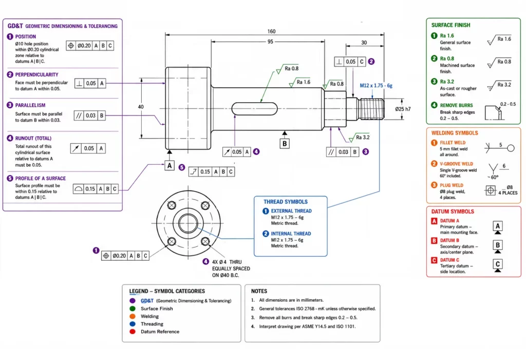
Engineering drawing symbols cover far more than simple dimensions. They communicate geometric tolerances, surface texture requirements, welding instructions, hole specifications, datum references, material conditions, inspection criteria, manufacturer methods, and more. The depth of communication and effectiveness of drawings is governed by formal standards – ASME Y14.5-2018, ISO 128, and ISO 1302. These internationally recognized authorities ensure that the meaning of every symbol remains consistently clear and unambiguous for all.
This guide explains the most important engineering drawing symbols used in manufacturing, with a close focus on the meaning of those symbols to machinists, inspectors, and suppliers. Rather than simply defining each symbol, we will examine how influences from the symbols flow outward into manufacturing methods, measurement techniques, inspection costs, and overall part quality.
Key takeaways
- Engineering drawing symbols are governed by standards from the ASME (American Society of Mechanical Engineers) and ISO (International Organization for Standards) bodies, and interpretations across-standards are themselves governed cohesively.
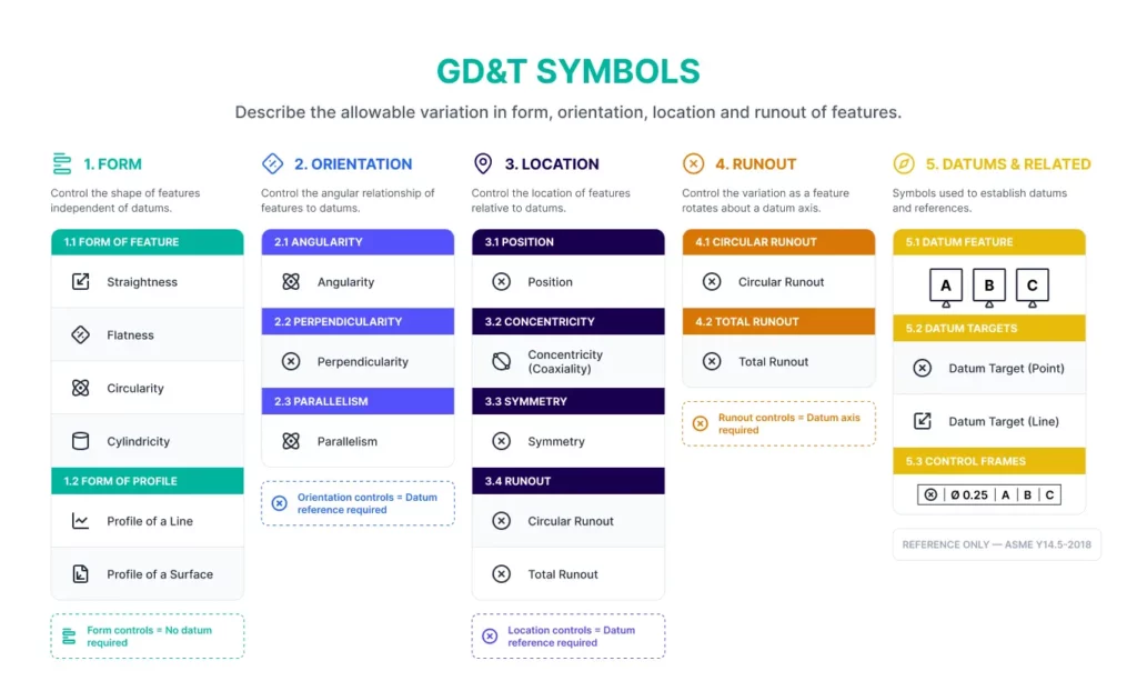
- GD&T symbols control form, orientation, location, profile, and runout – and most significantly, tolerances that are essential for functional assemblies.
- Surface finish references define quantified surface texture requirements and their assessment/making basis, not primarily cosmetic appearance.
- Datum systems establish the reference framework used to manufacture and inspect parts, minimizing incoherent relative measurements and tolerance stacking.
- The most common source of tolerance disputes is ambiguous drawing annotation/interpretation rather than incorrect machining.
- Tightening tolerances beyond functional requirements can significantly increase manufacturing and inspection costs while adding zero value, where well expressed dimensioning can often enable more relaxed constraints.
What are engineering drawing symbols?
Engineering drawing symbols are standardized graphical notations used on annotated component-drawings, to communicate dimensions, geometric requirements, tolerances, surface conditions, manufacturing instructions, material specifications, applicable standards, process requirements, and inspection criteria.
The hazard in relying primarily on written notes is divergent language skills and ambiguity of meaning, even within a common language. Symbols provide the semiotics for a universally clear shorthand.
For example, a simple diameter symbol instantly communicates that a dimension applies to a circular feature, while a GD&T position symbol communicates a complex tolerance zone relationship that might otherwise require multi-sentence explanation.
Engineering drawings combine multiple symbol categories:
- Geometric Dimensioning and Tolerancing (GD&T)
- Surface finish symbols
- Hole and thread callouts
- Welding symbols
- Datum references
- Technical line conventions
- Projection symbols
- Material and process notes
Together these symbols form a complete manufacturing specification.
Why engineering symbols are important
Natural language is inherently ambiguous. An instruction such as “make this surface smooth” provides little useful information to a machinist or inspector. By contrast, specifying a surface finish of Ra 0.8 μm communicates an exact measurable requirement, particulary when coupled with additional information about lay, waviness, and assessment method.
Engineering symbols eliminate interpretational variability throughout the manufacturing chain. Designers, machinists, quality inspectors, and suppliers can all use the same reference standard and definitions.
Universal communication standards
A supplier in one country may never speak directly with the engineer who created the drawing. Symbols provide a common language that transcends geography and language barriers.
Manufacturing accuracy
Symbols define the methodology of how a part is to be manufactured. Without this clarity of specification, dimensional, tolerance, positioning, and characteristic variation increases, and assembly performance becomes less tightly predictable.
Quality control and inspection
Inspection personnel rely on symbols to determine the features that require measurement, the precision required, and by extension the instruments that must be used in assessing a part.
A flatness requirement of 0.02 mm may require a granite surface plate and dial indicator height-gauge, while a positional tolerance of 0.01 mm will likely require a coordinate measuring machine (CMM).
Engineering drawing standards
Engineering drawing symbols are governed by rigid standards. Understanding which standard applies to a drawing element and aspect under its control is essential, because symbol interpretation diverges, often in intricate ways, between standards.
The title block should always be reviewed before interpreting dimensions or tolerances, to calibrate the reader’s understanding of the symbols.
ASME Y14.5 standard
ASME Y14.5 is the dominant GD&T standard used throughout North America, and therefore also well understood by anyone in the manufacturing supply chain that acts as service provider to US companies.
It defines:
- Geometric tolerances
- Datum systems
- Feature control frames
- Material condition modifiers
- Drawing conventions
U.S. aerospace, defense, automotive, and industrial manufacturers adhere to ASME Y14.5.
ISO standards
ISO drawings commonly rely on:
- ISO 128 – line conventions
- ISO 1101 – GD&T
- ISO 1302 – surface texture
- ISO 5459 – datums
Although many symbols are similar to ASME equivalents, differences exist in interpretation and notation.
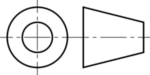
First-angle vs third-angle projection
One of the most important drawing symbols announces the projection system used in creating drawing layouts. First and Third Angle Projection use opposing spatial logic; third angle can be considered as “look through”, and first angle as “look at”, and understanding which a drawing is based on flows directly from the symbol. These systems must never be mixed in a drawing, as this can cause a reversal of features in the ambiguity of interpretation that results.
Note that there is no standard size for these symbols, and they can both be used in any orthogonal orientation, for identical meaning.
First-angle projection
Common in:
- United States
- Canada
- Suppliers worldwide, serving North American customers
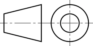
Third-angle projection
Common in:
Misinterpreting projection methods can result in features being manufactured on the wrong side of a component, or mirrored.
Geometric dimensioning and tolerancing (GD&T) symbols
GD&T designates allowable geometric variations in manufactured parts.
Unlike more basic plus/minus tolerancing, GD&T controls functional relationships between features according to preset ranges/parameters.
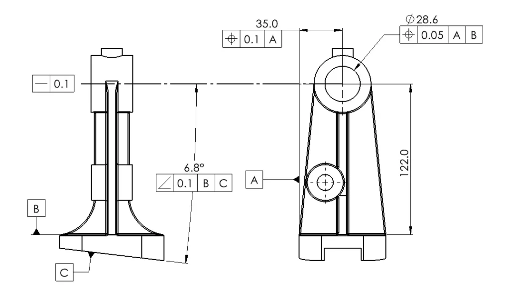
Central to GD&T is the Feature Control Frame.
- Geometric characteristic: Position
- Tolerance zone: Ø0.05
- Primary datum: A
- Secondary datum: B
- Tertiary datum: C
- Straightness – no datum reference
Datum reference systems
Datums establish the coordinate reference basis used for manufacturing and inspection. The reference frame is critical, as it defines all of the relationships that flow from it. Over-referencing can create interpretation difficulties, where under-referencing can undermine the desired precision by missing critical aspects.
Primary datum
Controls three degrees of freedom. A primary datum plane constrains three degrees of freedom: translation perpendicular to the plane and rotation about two axes lying within the plane. The part can no longer move relative to the surface or rock on two orthogonal planes, establishing a stable reference.
Secondary datum
Controls two additional degrees of freedom. A secondary datum constrains: translation along one axis within the primary datum plane and rotation about the axis perpendicular to both datums. The part can no longer slide in that direction or rotate around the primary datum.
Tertiary datum
A tertiary datum constrains the final remaining degree of freedom: translation along the last unconstrained axis. With the primary, secondary, and tertiary datums established, the part is fully located in space and all six degrees of freedom (translation x 3 and rotation x 3) are constrained.
Effective datum selection often determines whether a part can be manufactured reliably/precisely and then inspected economically. Hard to use datums can greatly increase the cost of inspection by requiring significant upgrade in equipment for QA.
From control symbols
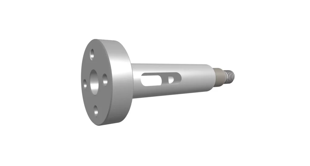
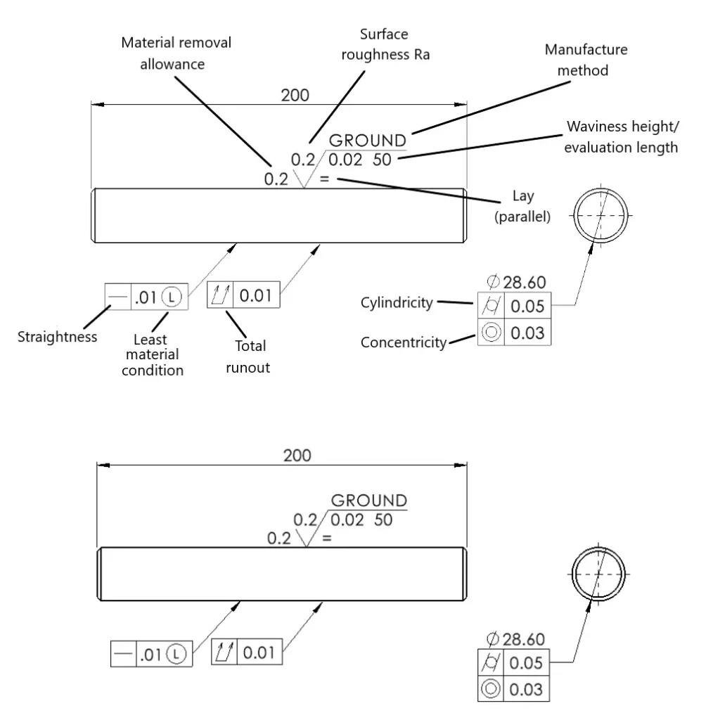
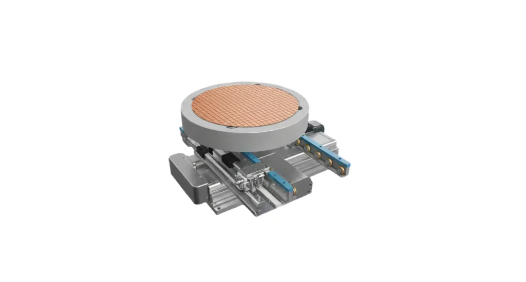
Form controls define the shape of a single feature without reference to datums. While a piece of ground stainless steel shaft for a linear guide is a simple component, it can require considerable information to ensure it meets the required standards in all regards
Straightness
Controls how straight a feature must be.
Common applications:
- Shafts
- Guide rails
- Linear bearing surfaces
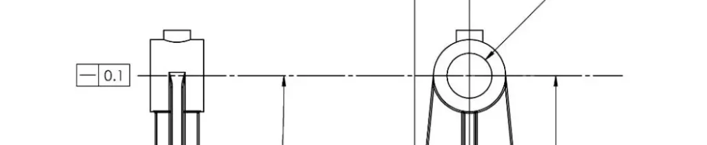
Flatness
Controls how flat a surface must be.
No datum reference is required.
Common applications:
- Sealing faces
- Mounting surfaces
- Precision machine bases
Waviness
Controls variation in surface height over a sampling length.
No datum reference is required.
Common applications:
- Sliding bearing elements
- Linear guides
Circularity (roundness)
Controls roundness of circular features.
Frequently applied to:
- Bearing journals
- Valve stems
- Precision shafts
Cylindricity
Controls the overall cylindrical form.
Common in:
- Hydraulic cylinders
- Bearing surfaces
- Rotating components
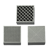
Lay
Controls the orientation of surface features remaining after machining/finishing.
Common applications and types:
- Cylindrical – rotating bearing surfaces
- Linear/parallel – sliding bearing surfaces
- Multi directional – unpredictable motion, general smoothness
Profile
Profile tolerances control complex surfaces.
Common applications:
- Castings
- Forgings
- Aerospace components
- Turbine blades
Orientation control symbols
Orientation controls define angular relationships relative to datums.
Perpendicularity
Controls 90° relationships.
Common examples:
- Hole axes relative to mounting surfaces
- Precision machined shoulders
Parallelism
Controls parallel relationships.
Common examples:
- Slideways
- Bearing surfaces
Angularity
Controls any specified angle relative to a datum.
Often used where exact angular relationships affect assembly performance.
Location control symbols
Location controls define where features must be positioned.
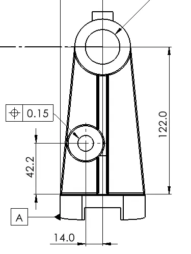
Position
Position is the most widely used GD&T control.
It defines a tolerance zone around the true location of a feature.
Typical applications:
- Bolt patterns
- Dowel holes
- Bearing locations
True position
True position is often misunderstood as simply an X-Y tolerance.
In reality, it creates a cylindrical tolerance zone that provides significantly better control of feature functionality.
This allows manufacturers more flexibility while assuring component performance.
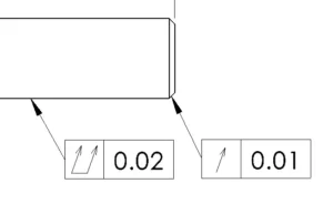
Runout symbols
Runout controls are used primarily on rotating components where concentricity, balance, and smooth operation are critical.
Circular runout
Circular runout controls variation in a single circular cross-section as the part rotates around its datum axis.
Common applications:
- Pump shafts
- Bearing journals
- Valve stems
- Rotating couplings
A circular runout tolerance helps ensure smooth rotation and reduces vibration.
Total runout
Total runout controls variation across the entire surface of a rotating feature.
Unlike circular runout, which evaluates individual sections, total runout evaluates the complete surface simultaneously.
Common applications:
- Precision rollers
- High-speed shafts
- Turbine components
- Aerospace rotating assemblies
Total runout is typically more difficult and expensive to inspect and often requires specialized metrology equipment.
Basic dimension symbols
Dimension symbols communicate measurement types quickly and consistently.
Misinterpreting these symbols frequently results in incorrectly manufactured features.
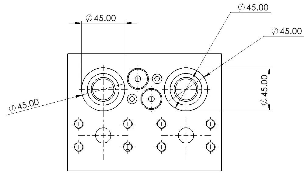
Diameter (Ø)
Indicates a circular feature’s diameter.
One of the most common drawing mistakes is reading a diameter dimension as a radius requirement.
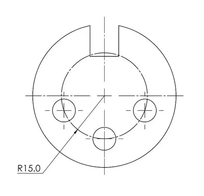
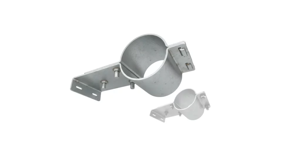
Radius (R)
Defines the radius of an arc or curved feature. In this example, it defines the radius of a pitch circle on which three drilled holes lie.
Depth
Used to indicate the depth of drilled, bored, or machined features.
Example:
Ø30 × 20 DEEP
Meaning:
30 mm diameter hole extending 20 mm into the part.
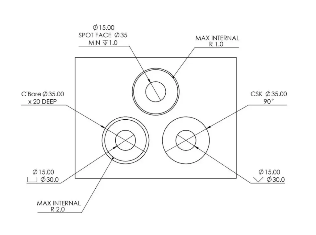
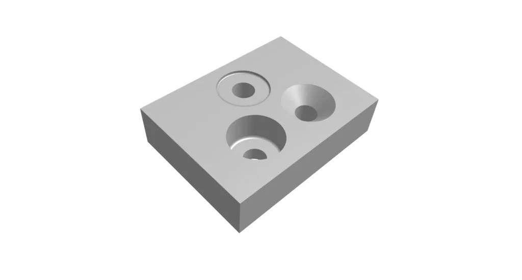
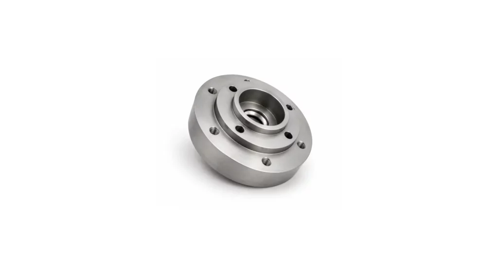
Counterbore
Counterbores create flat-bottomed recesses for bolt heads or fasteners.
Common callout:
Ø12 C’BORE Ø20 × 5 DEEP
Frequently used with socket-head cap screws.
Countersink
Countersinks create conical recesses.
Example:
Ø10 C’SINK 90°
Used for flat-head screws.
Spotface
A shallow machining operation that creates a flat seating surface.
Commonly used on castings and forgings where bolt heads or washers require a stable bearing surface.
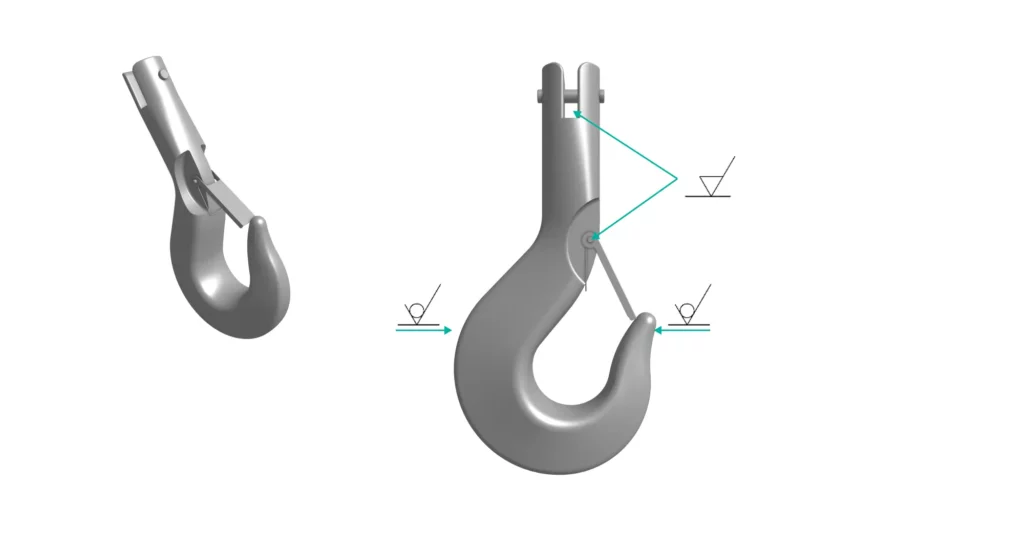
Surface finish symbols
Surface finish symbols communicate allowable surface texture and often have significant manufacturing cost implications.
Many engineers underestimate how dramatically surface finish requirements influence process selection, cycle time, and inspection costs.
A sealing face specified at Ra 0.4 μm may require grinding or lapping, while a general machined surface specified at Ra 3.2 μm may be achievable through standard milling operations.
Surface roughness
Surface roughness is typically specified using Ra.
Common values:
Other surface parameters
Rz
Measures average peak-to-valley height.
Widely used throughout Europe and many ISO-based industries.
Rt
Measures total profile height.
Common in sealing applications.
Waviness
Controls larger-scale surface variation beyond roughness.
Important in precision sealing and optical applications.
Material removal required
A bar added to the surface finish symbol indicates material removal is required.
This typically means:
- Milling
- Turning
- Grinding
- Honing
must be performed.
No material removal allowed
A circle added to the symbol indicates material removal is prohibited.
Common applications:
- As-cast surfaces
- As-forged surfaces
- Cosmetic molded surfaces
Surface finish cost
Surface finish is one of the most commonly over-specified drawing requirements.
Reducing a requirement from Ra 0.8 μm to Ra 3.2 μm can significantly lower machining costs without affecting part function, if the application does not require a highly finished surface.
Technical line symbols
Line types are not stylistic choices. Each line type carries a specific meaning.
Misreading a line type can result in hidden features being overlooked or incorrectly manufactured.
Visible lines
Thick continuous lines representing visible edges.
These define the geometry that can be directly seen in the drawing view.
Hidden lines
Short dashed lines representing obscured features.
Examples:
- Internal holes
- Internal cavities
- Hidden slots
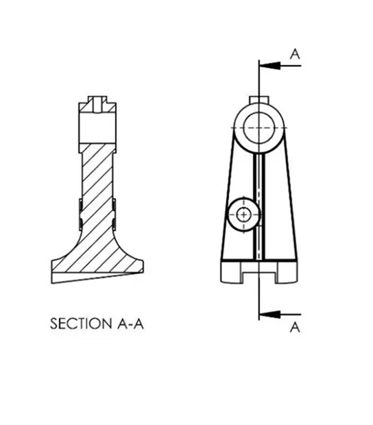
Cutting plane lines
Used to indicate where a sectional view has been taken.
Critical for understanding internal geometry.
Centerlines
Long-short-long chain lines representing:
- Symmetry axes
- Hole centers
- Rotational axes
Centerlines often become datum references during manufacturing and inspection.
Specialized engineering symbols
Many industries introduce specialized symbol sets beyond standard mechanical drawings.
Welding symbols
Welding symbols communicate:
- Weld type
- Weld size
- Weld location
- Weld length
Common examples:
Incorrect interpretation can compromise structural integrity.
Thread symbols
Thread callouts are among the most common manufacturing symbols.
Examples:
- M10 × 1.5
- M12 × 1.75
- 1/4-20 UNC
- 1/4-28 UNF
- 1/2 NPT
- BSPP
- BSPT
Thread designation defines both diameter and pitch.
Electrical symbols
Electrical drawings introduce symbols representing:
- Switches
- Relays
- Connectors
- Resistors
- Grounding points
These differ significantly from mechanical drawing conventions.
P&ID symbols
Process and Instrumentation Diagrams use symbols representing:
- Valves
- Pumps
- Compressors
- Instrumentation
- Flow control devices
Common in chemical processing, energy, and oil and gas industries.
Commonly misunderstood engineering drawing symbols
Many manufacturing disputes originate from symbol interpretation rather than machining errors.
Position vs coordinate tolerance
Position tolerances create geometric tolerance zones rather than simple X-Y variation limits.
Flatness
Flatness controls surface form only.
It does not require a datum.
Profile
Profile controls surface shape.
It does not directly control feature size.
Counterbore vs countersink
Counterbores are cylindrical.
Countersinks are conical.
Confusing the two often results in unusable parts.
Surface finish
Surface finish symbols specify measurable roughness requirements rather than cosmetic appearance.
Inspection methods for common symbols
Different symbols require different inspection methods.
One of the most common causes of supplier frustration is specifying tolerances that require expensive inspection equipment without recognizing the associated cost impact.
Tolerance stack-up
Even when every dimension is within tolerance, assemblies may fail due to cumulative variation.
Worst-case stack-up
Assumes every dimension reaches its maximum allowable variation simultaneously.
Statistical stack-up
Uses probability-based calculations to predict likely variation.
Engineers should evaluate stack-up whenever multiple dimensions contribute to a functional assembly relationship.
How to read an engineering drawing
Reading a drawing should follow a systematic process.
Jumping directly to dimensions often leads to incorrect interpretation.
Understanding title blocks
Review:
- Drawing number
- Revision level
- Material specification
- Governing standard
- Scale
- Units
Always verify revision status before manufacturing.
Scale and projection methods
Confirm whether the drawing uses:
- First-angle projection
- Third-angle projection
before interpreting views.
Datum references
Identify the primary, secondary, and tertiary datums.
Understanding the datum structure often explains how the part is intended to function.
Review critical characteristics
Identify:
- GD&T callouts
- Surface finish requirements
- Thread specifications
- Critical dimensions
before beginning manufacturing.
Evaluate inspection requirements
Determine whether specified tolerances can be measured using available equipment.
This step alone can prevent costly quality disputes.
Common engineering drawing abbreviations
Conclusion
Engineering drawing symbols transform design intent into manufacturable reality. They provide the standardized language that connects engineers, machinists, inspectors, and suppliers throughout the manufacturing process.
Understanding symbols requires more than memorizing definitions. Engineers must understand what each symbol means for manufacturing, inspection, cost, and functionality. A flatness tolerance influences inspection strategy. A surface finish callout influences process selection. A position tolerance influences fixture design and metrology requirements.
The most successful manufacturing projects occur when engineers and suppliers interpret drawings consistently and communicate early about potentially ambiguous requirements. Reviewing GD&T callouts, surface finish specifications, datum structures, and inspection methods before production begins reduces risk, prevents tolerance disputes, and helps ensure parts arrive right the first time.