
Engineering drawings exist to communicate precision. If the outcome is not precise according to the specification expressed as a drawing, generally a manufacturing error is blamed.
Hold your horses. Yes, there is always the risk that the manufacturer didn’t follow the information in the drawing precisely. However, there is a whole layer of issues that arise from poor understanding in the draftsperson as to HOW to express the design intent.
To be clear, this is an area that many engineers have limited (sometimes no) knowledge of and it is often neglected (“Oh I don’t need that stuff, the supplier knows what I want”) or excitedly over-specified as part of a FAFO learning process.

Datum reference frames were developed to try to circumvent some of the minefield of misunderstandings that can develop between drawing and part, creating false positives at inspection sometimes – but false rejections more often. This can best be illustrated by a clear false negative that can come from simplified datum points and orthogonal thinking;
In the 1940s, weapons engineer Stanley Parker observed this issue while attempting to measure torpedo components to see why they failed inspection and yet served perfectly. Over the decade to 1950, Parker created the initial approach to defining datum reference frames, altering the nature of engineering documentation forever.
There are two applicable standards for datums within GD&T – the ASME (Ref: Y14.5M) and ISO (ISO/CD 5459-2 to ISO/CD 5459-4) standards.
Precision, consistency and readability are critical in component level documentation in ensuring that manufactured parts fit and function according to the design intent. But they are also easy to overspecify. Overly cautious or poorly understood tolerancing and datums can result in serious price-consequences, by pre-defining higher precision processes and manufacturing methods that drive up costs, for no benefit.
The selection of an appropriate Datum Reference Frame (DRF) is perhaps the most fundamental tool in Geometric Dimensioning and Tolerancing (GD&T). It establishes the standardized coordinate system for defining the location and orientation of features on a part, to allow the precision to be both relevant and sufficient unto the application. It provides a stable reference for manufacturing, inspection, and assembly, ensuring that all components are produced and measured consistently.
By selecting a well-defined and function-appropriate DRF, the designer can achieve necessary accuracy, repeatability, and efficiency in product design and manufacturing, making DRFs the essential starting point of all engineering drawing dimensioning.
Understanding Datum Reference Frames
What is a Datum?
In engineering drawings, a datum is a (theoretically invariant) reference feature – such as a plane, axis, hole center, or point – used as a starting location from which dimensions are defined and validating inspection measurements are confirmed. It provides a consistent baseline for defining the size, orientation, and position of features on a part. Datums are an essential starting point for a useful execution of GD&T. Datums ensure precision, repeatability, and consistency in manufacturing and inspection and enable assessments of parts that are as dimensionally maximally relaxed as the design intent and product function allow.
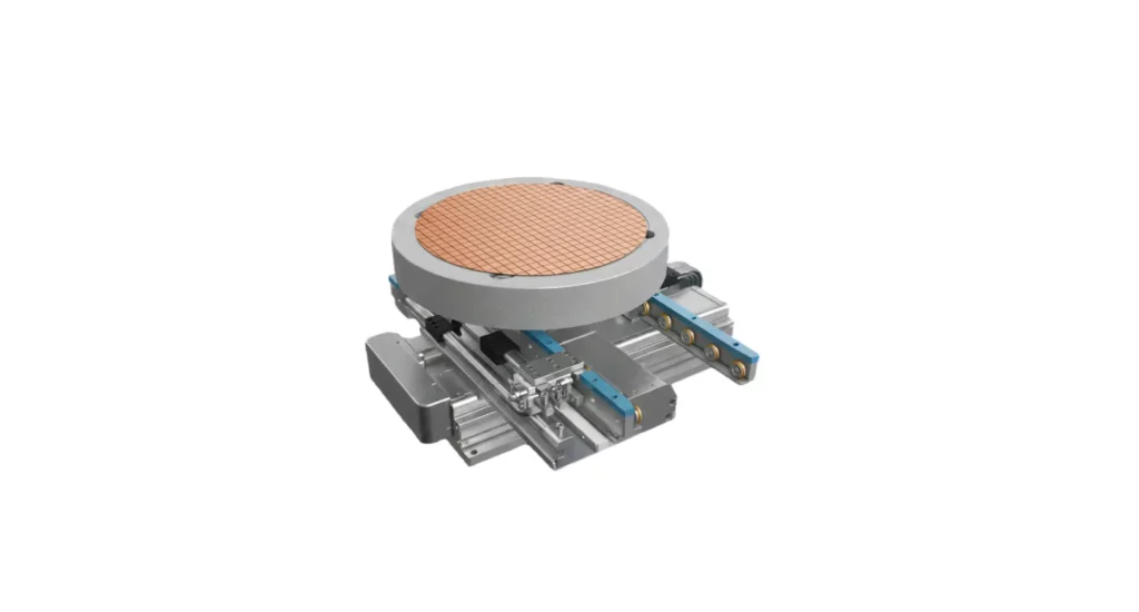
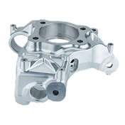
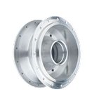
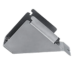
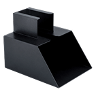
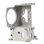
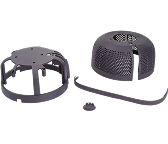
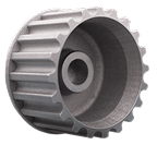
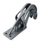
Datum selection is directly based on the functional requirements of a part. For example, the V-block swivel below, the most critical aspects are:
- That the T-slot feature and swivel engage smoothly and travel freely, with minimal diametral backlash
- That the axis of this swivel is orthogonal to the base and end faces (reference faces A and B) of the product and parallel to the C reference face, to reference precisely to a machining centre table
- That the reference angles etched into the two components correspond precisely to the underside reference face B so that angle settings are reliable
Datums help control form, orientation, and location tolerances, reducing ambiguity in measurement.
By defining datums, engineers establish standardized terms of reference, so all parts are produced and measured against the same geometric foundation, minimizing errors in machining, assembly, and quality control.
What is a Datum Reference Frame?
A Datum Reference Frame (DRF) is a three (or more) dimensional coordinate system used in engineering drawings and GD&T to fully constrain feature locations and orientations. It consists of three or more datums – primary, secondary, and tertiary, plus auxiliary local datums – that collectively constrain six degrees of freedom (three translational and three rotational), ensuring accurate feature positioning for manufacturing and inspection.
- Primary Datum (Datum A): Establishes a stable base, restricting two or three degrees of freedom. In our example, the end face is chosen as the most dimensionally critical for physical positioning of the V-block onto a work table.
- Secondary Datum (Datum B): Constrains two more degrees of freedom. In our example, the orthogonality of the device to the machine table (Ref:A) is of the same importance as as the height-above-table (Ref:B)
- Tertiary Datum (Datum C): Controls the final degree of freedom, fully defining the part’s spatial position. This is critical both in positioning the V-Block as orthogonal to the machine AND confirming that the axis of rotation of the swivel is parallel to the base of the device in two axes. In some regards, the swivel axis can be seen as an auxiliary datum for the GD&T process.
An appropriately-defined DRF ensures that parts are consistently measured, machined, and assembled according to the same references, reducing errors and improving precision. It is essential in complex assemblies, where multiple components must align both within the assembly and to external reference faces/points accurately, in order to function effectively.

Constructing a Datum Reference Frame
A DRF is a structured system of three (or more) datums that fully define the position and orientation of features of a part, under GD&T guidelines and standards. Constructing a DRF ensures accurate manufacturing, inspection, and assembly by eliminating/constraining all six degrees of freedom (three translations and three rotations).
Steps to Construct a Datum Reference Frame:
- Select the Primary Datum (Datum A):
Choose the most stable and functionally significant surface, typically a large, flat face or mounting face. This datum generally restricts three degrees of freedom (translation along Z, rotation about X and Y).
- Select the Secondary Datum (Datum B):
Typically, an edge or a hole that provides a perpendicular reference to Datum A. It removes two additional degrees of freedom (translation along Y, rotation about Z).
- Select the Tertiary Datum (Datum C):
A feature that stabilizes the part’s final orientation, such as a secondary perpendicular surface or another hole. It restricts the last degree of freedom (translation along X).
Once established, these datums define a consistent coordinate system, ensuring precise measurement, repeatability, and proper alignment in multi-part assemblies. A correctly constructed DRF improves manufacturing accuracy and quality control while reducing errors.
Guidelines to choosing Datum Features
Selecting the most appropriate datum features is key to ensuring accuracy, repeatability, and manufacturability in GD&T. These are typical steps in optimal choice of datum features:
Choose functionally relevant features
Select surfaces or features that play a critical role in the part’s function or assembly. This suggests the prioritization of features that define mating surfaces, alignments, or load-bearing functions.
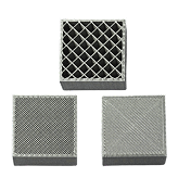
Ensure stability and accessibility
Use large, stable, and either flat or regularly cylindrical surfaces to control variation and error in measurement. Ensure datums are easy to access for machining center probes, inspection equipment, and assembly.
Minimize measurement and setup errors
Avoid small, irregular, or easily deformable/flexible features as datums. Select features that can be easily referenced during machining and quality control, for intermediate (during machining) and validation checks.
Restrict degrees of freedom effectively
The primary datum selected must deliver a stable reference and ideally constrain three degrees of freedom. The Secondary and Tertiary Datums must then fully constrain the part without introducing ambiguity.
Align with Manufacturing and Inspection Processes
Datums are selected to align with fixturing for machining, fitment in a follow-on assembly and measurement for inspection. Compatibility with Coordinate Measuring Machines (CMMs) and other inspection tools is a must-have.
Practical examples
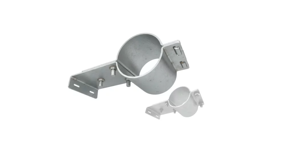
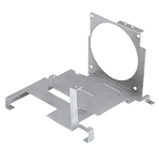
Machined bracket
Application: A steel mounting bracket used to attach components in a machine assembly process.
Datum Selection:
- Primary Datum (Datum A): The large, flat mounting face where the bracket attaches to the frame.
- Secondary Datum (Datum B): A machined hole used for a bolt, ensuring axial alignment.
- Tertiary Datum (Datum C): A perpendicular edge/face that defines the component orientation.

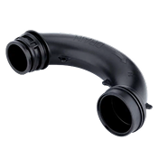
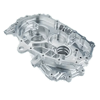
Automotive engine block
Application: A precision-machined engine block, in which a range of cylinder axes, mounting points, and gallery entry/exits must align with secondary components.
Datum Selection:
- Primary Datum (Datum A): The machined base surface where the block attaches to the lower crank-case or sump.
- Secondary Datum (Datum B): A bore hole for the crankshaft, ensuring proper alignment of crank to cylinders.
- Tertiary Datum (Datum C): A machined side surface to maintain, in this example, the V-profile features relative angle(s).
Purpose: Ensures accurate placement of internal components like pistons and camshafts, minimizing vibration and wear.

Common mistakes in DRF selection
Selecting an unstable or deformable primary datum
- Error: Choosing a surface that is small, flexible, or prone to deformation (e.g., thin sheet metal or a rough casting surface).
- Consequence: Leads to measurement inconsistencies, poor repeatability, and misalignment during assembly.
- Solution: Select a large, rigid, and functionally relevant surface that provides a stable base for measurement and manufacturing.
Overconstraining or underconstraining the DRF
- Error: Defining too many or too few datums, leading to conflicts or incomplete constraints.
- Consequence: Overconstraining results in conflicting constraints that make manufacturing and inspection difficult or affect interpretations that result in error. Underconstraining results in ambiguity and error.
- Solution: Follow the three-plane rule, use 3 primary datums that are either orthogonal or highly functionally significant.:
Choosing datums that fail to reference external functional issues.
- Error: Selecting datum features based on ease of evaluation, not real-world assembly/fit requirements.
- Consequence: Parts may pass inspection but fail in actual assembly, due to misalignment with mated parts.
- Solution: Define datums based on the detailed process whereby the part is actually assembled and used, ensuring alignment with functional requirements.
Best practices for defining DRFs
Employ functionally critical features as datums – select surfaces or features that are primarily responsible for part performance and assembly relationships.
Ensure datum feature stability and repeatability – choose large, rigid, and easily accessible surfaces to ensure easy measurement and consistency.
Follow an effective constraint order – consider manufacturing and inspection needs early, review regularly – ensure datums align with fixturing and measurement methods like CMMs.
- Primary datum: Most critical surface, restricts 3 DOF.
- Secondary datum: Provides perpendicularity, restricts 2 DOF.
- Tertiary datum: Completes constraint, restricting the final DOF.
Avoid Ambiguity
- Clearly label datums in drawings using appropriate GD&T symbols and clear constraint references to prevent misinterpretation.
Conclusion
At its heart, the DRF process in defining manufacturing and inspection criteria for manufactured parts is a keystone that holds quality management processes in place. Without the near 100 years of learning that has evolved this system, the uncertainties involved in reproducibility and tight control of part quality and assembly procedures are degraded and we return to a more approximate, trial and error based approach to part definitions.
It is a smart response to a wide range of potential difficulties in product/component definition and GD&T and it is surprisingly poorly understood in many areas of the design community, requiring a learn-through-error approach that costs time and money.
Better understanding of the symbiosis between GD&T and DRF is the key to quality, and this should not be under-applied – or OVER applied!.