
Direct Metal Laser Sintering (DMLS) is a metal 3D printing process that applies a high-powered laser to point-fuse fine metal powders, ‘drawing’ layers and fusing layers together to build dense, functional parts. This operates through a specialist CAM software process that slices parts directly from CAD data, and requires no tooling.
DMLS belongs to the powder bed fusion (PBF) family of additive manufacturing technologies, one of the earliest approaches to additive manufacture, beginning as SLS (selective laser sintering) to build nylon parts.
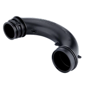
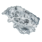
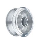
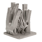
This metal process is increasingly called upon when engineers need complex, near-net-shape geometries that are difficult, expensive, or even impossible to manufacture via CNC machining, casting, or fabrication. Features such as internal cooling channels, partially buried or open lattice structures, or the consolidation of multi-part assemblies are essentially impossible by more traditional processing methods, but simple to execute and design empowering through DMLS.
Key takeaways
- DMLS uses a high-powered laser to fuse metal powder point by point and layer by layer, creating functional parts directly from CAD, without tooling.
- The process commonly achieves ~99%+ density, with mechanical properties comparable to wrought/forged alloys when processed and heat treated appropriately.
- DMLS enables astonishing and design-unleashing complexities in geometry, including internal channels, weight reduction and stress dissipation lattice structures, freeform organic shapes, and re-entrant and graded and auxetic structures that are entirely impractical through traditional manufacturing.
- Common DMLS materials include Ti-6Al-4V, 316L and 17-4 PH stainless, AlSi10Mg, Inconel 718, cobalt-chrome, and maraging steel. Though choices are limited, available options are steadily increasing.
- Post-processing is typically required: support removal, stress relief/heat treatment, machining critical surfaces, and surface finishing
What is Direct Metal Laser Sintering (DMLS)?
DMLS is metal additive manufacturing in which a laser selectively fuses metal powder spread in thin layers across a build plate. The fusion aims for full liquefaction of particles, despite the name including sintering. After each layer, or slice, of a build is fused, the machine spreads another layer of powder and repeats the process until the part is complete.
Historically, DMLS aimed for sintering, fusing powder particles at their contact points without fully melting them. Related terms like selective laser melting emphasize full liquefaction. In modern practice, most DMLS-class machines produce parts that are effectively fully fused (near-fully melted) for high density, and the terms are frequently used interchangeably in industry.
DMLS is best understood as a way to manufacture dense, net-shape metal parts without tooling, enabling:
- Complex internal structures.
- Part consolidation, merging assemblies into single printed components.
- Rapid design iterations without retooling.
- Lightweighting through topology optimization and lattice infill.

How does DMLS work?
Step 1: CAD model preparation and slicing
Engineers prepare a CAD model, then the build is “sliced” into thin layers in specialist CAM (slicer) software. This step also defines:
- Support strategy
- Build orientation relative to layering
- Layer thickness and therefore build-speed and end-result precision in local features
- Allowances for machining critical surfaces, in hybrid processes
Step 2: Build chamber setup
The machine build chamber is typically filled with inert gas (commonly argon or nitrogen depending on alloy) to reduce oxidation during fusion. The build plate is installed and leveled, and powder is loaded.

Step 3: Powder deposition
A recoater spreads a uniform layer of metal powder across the build area. Layer thickness is commonly on the order of tens of microns, depending on machine and alloy.

Step 4: Laser fusion
A laser scans the cross-section for that layer, fusing powder where the part exists. The scan strategy (hatch patterns, contours, energy density) strongly influences:
- density and porosity
- surface quality
- residual stress
- microstructure and anisotropy
Step 5: Layer-by-layer building
The build platform lowers slightly, another powder layer is spread and skimmed to height, and the laser fuses the next cross-section and inter-layer junction. This repeats until the part is complete.
Step 6: Part removal and powder recovery
After the build, unused powder is recovered (often sieved and recycled within specification). The part is removed from the powder cake, and then separated from the build plate (commonly by wire EDM or machining). Powders represent significant health hazards, if not correctly handled.
The role of support structures
Supports are not optional “extras”—they are structural and thermal tools. Supports:
- anchor overhangs and prevent distortion
- conduct heat away from the part
- reduce residual stress and warping
Support removal is part of post-processing cost and should be considered early in design. Supports enhance build rigidity in overhangs and delicate features, but can pose challenges in post-processing.
What are the best materials for DMLS?
DMLS supports a strong portfolio of industrial alloys. Material selection should consider not only strength and corrosion resistance, but also:
- heat treatability and post-processing route
- fatigue requirements
- operating temperature
- printability constraints (cracking risk, support needs, distortion risk)
Titanium (Ti-6Al-4V)
High strength-to-weight, corrosion resistant, and biocompatible—excellent for aerospace and medical.
Stainless steel (316L, 17-4 PH)
- 316L: corrosion resistance, good ductility
- 17-4 PH: precipitation hardening for higher strength with heat treat
Aluminum (AlSi10Mg)
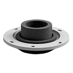
Lightweight, good thermal behavior, common for housings and lightweight structures.
Inconel 718
A high-temperature nickel superalloy used for demanding thermal and corrosion environments (turbine-adjacent parts, hot-section support components).
Cobalt-chrome
Highly wear resistant and biocompatible; common in dental and orthopedic implants.
Maraging steel
Very high strength after heat treatment; often used for tooling and high-stress components.
Material selection considerations
Choose a material based on:
- service loads and fatigue behavior
- corrosion/chemical exposure
- temperature and creep requirements
- regulatory and traceability requirements
- availability of validated parameter sets at the supplier
| Material | Key Properties | Typical Applications |
|---|---|---|
| Ti-6Al-4V | High strength-to-weight, corrosion resistant, biocompatible | Aerospace brackets, medical implants |
| 316L Stainless | Corrosion resistant, good ductility | Medical devices, chemical processing |
| 17-4 PH Stainless | High strength, heat treatable | Aerospace, industrial components |
| AlSi10Mg | Lightweight, good thermal conductivity | Housings, aerospace/auto structures |
| Inconel 718 | High-temp strength, corrosion resistant | Turbine-related components, aerospace |
| Cobalt-Chrome | Biocompatible, wear resistant | Dental, orthopedic implants |
| Maraging Steel | Very high strength after heat treat | Tooling, high-stress parts |
What are the advantages of DMLS?
Complex geometry capabilities
DMLS enables internal channels, conformal cooling, lattice structures, and organic surfaces that are not feasible via subtractive methods.
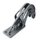
Design freedom and optimization
Engineers can use topology optimization to remove mass where it isn’t structurally required, then print geometries that would be impossible to machine.
Functional metal prototypes
You can validate real material performance early. This is especially valuable when high-temperature strength, corrosion resistance, or load-bearing properties are required.
Reduced lead times vs Traditional manufacturing
For complex parts, DMLS can eliminate tooling lead times and reduce supply chain steps—especially when casting or multi-operation CNC would be required.
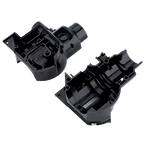
Part consolidation benefits
DMLS often enables replacing assemblies with a single part:
- fewer fasteners
- fewer leak paths
- fewer tolerance stack-ups
- faster assembly
This can often present design opportunities and significant cost reductions, compensating for the essentially slower and more expensive processing that the method entails.
Material efficiency
Compared to machining from billet, DMLS can reduce buy-to-fly ratio (especially in aerospace alloys), though powder cost and post-processing must be accounted for.
What are the disadvantages and limitations of DMLS?
Cost considerations
DMLS parts can be expensive per unit due to machine time, powder cost, and required post-processing. It tends to win when complexity is high or when tooling cost is prohibitive.
Surface finish limitations
As-printed surfaces are typically rougher than machined surfaces. Cosmetic, fit, or sealing surfaces often require machining, polishing, or surface finishing.
Build size constraints
Build volumes are finite. Large components may need to be segmented or built with other processes.
Post-processing requirements
Common post-processing steps include:
- stress relief or heat treatment
- support removal
- machining of interfaces and tolerances
- surface finishing (shot peen, bead blast, polish)
- inspection and (for critical parts) mechanical testing
Material limitations vs Traditional methods
Not every alloy is equally printable, and even for printable alloys, properties depend heavily on process control and validated parameter sets.
DMLS vs. SLM: Key differences
Sintering vs Full melting
Traditionally:
- DMLS referred to sintering (fusing without full melting)
- SLM referred to full melting
In current industrial reality, most current-tech machines and parameter sets marketed as DMLS achieve near-full melting to maximize density and mechanical performance.
Material compatibility
Both processes overlap heavily in materials; in practice, compatibility depends more on the machine, powder, and validated settings than on the label.
Practical differences today
Today, DMLS and SLM are often used interchangeably in conversation. What matters operationally is:
- part density and porosity targets
- mechanical property requirements
- heat treatment route
- quality documentation and testing
Design considerations for DMLS parts
Designing for DMLS isn’t design as usual. The best outcomes come from designing for:
- support minimization
- stable build orientation
- predictable post-processing
- realistic tolerances (with machining allowances where needed)
Minimum feature sizes
Minimum feature size depends on alloy and supplier capability, but practical guidance includes:
- avoid extremely thin pins or unsupported knife edges
- ensure features can be cleared of powder where needed
- plan machining for precise small bores or threads
Wall thickness guidelines
Thin walls are possible, but stability and distortion risk rises quickly. Use thicker walls where:
- the part must be flat
- sealing faces exist
- post-machining is required
Overhang angles and support requirements
Overhangs often require support. Designing to reduce supports lowers cost and improves surface quality on critical faces.
Hole and channel design
Internal channels are a key strength of DMLS, but you must consider:
- powder removal (escape paths)
- minimum channel diameters
- internal surface roughness (flow effects)
Build orientation impact
Orientation affects:
- support quantity
- surface finish on key faces
- strength anisotropy (directional properties)
- distortion and residual stress
- inspection and machining access
When to choose DMLS vs. Traditional manufacturing
DMLS is ideal when
- internal channels, lattices, or organic shapes are required
- part consolidation eliminates assembly complexity
- quantities are low-to-medium and tooling ROI is poor
- lightweighting brings high value (aerospace, performance systems)
- supply chain speed matters and tooling lead time is unacceptable
Traditional manufacturing is better when
- geometry is simple and machining is fast
- volumes are high and tooling amortization wins
- extremely tight tolerances dominate the design (without machining allowances)
- surface finish requirements are extensive across all faces
- the part exceeds build volume and segmentation is not acceptable
Hybrid approaches
Many high-performing parts use hybrid manufacturing:
- DMLS for near-net shape complexity, with hybrid solutions for precision
- CNC machining for tolerances, sealing faces, bores, and threads
- heat treatment and finishing for mechanical performance and surface integrity
Sourcing DMLS parts: Supplier selection
DMLS outcomes vary widely by supplier—more than many buyers expect. Two suppliers may both “offer DMLS,” but differ dramatically in:
- validated parameter sets for specific alloys
- density and porosity control
- dimensional repeatability
- heat treatment knowledge
- post-processing and inspection capability
Key supplier assessment areas
1) Capability claims vs reality
Ask for proof: similar parts, similar materials, similar quality documentation. A supplier’s experience level matters as much as their machine brand.
2) Material verification and process control
For critical applications, confirm:
- powder certification and handling controls
- material certs, traceability, and batch control
- mechanical test data or witness coupons when required
3) Post-processing expertise
DMLS is only part of the deliverable. Validate:
- stress relief and heat treat route
- support removal workflow
- CNC machining capability (in-house or qualified partner)
- surface finishing options (bead blast, polish, peen, coating)
4) Design feedback and DFM
Good suppliers provide DFM on:
- build orientation strategy
- support approach
- risk features (thin walls, overhangs, trapped powder)
- suggested machining allowances and datum planning
Why Jiga’s approach helps
DMLS requires matching the part to suppliers with specific material experience, appropriate post-processing capabilities, and quality systems. Jiga’s capability-based matching and direct supplier communication reduces the risk of sending complex DMLS work to underqualified vendors—while improving design feedback, documentation quality, and project outcomes.
Summary
Direct metal laser sintering (DMLS) is a powder bed fusion metal 3D printing process that produces dense, functional metal parts directly from CAD, without any hard intermediaries such as tooling or jigs. It excels at complex geometries, internal channels, lattice structures, and part consolidation, making it valuable in aerospace, medical, automotive, and die and toolmaking. The tradeoffs are cost, surface finish, build size limits, and post-processing needs. Successful DMLS projects depend on smart DFM, especially build orientation and support strategy, and on selecting a supplier with proven material/process capability, post-processing depth, and quality documentation. Jiga supports this by connecting teams to vetted DMLS suppliers with direct communication and quality assurance.
DMLS is moving from niche to mainstream as resolutions and build quality improve, as material costs diminish, and as more materials become available.