
Face milling is one of the machining approaches used to create flat surfaces – it is differentiated by positioning of the cutter axis being perpendicular to the desired machined surface. This typically uses a multi-insert cutter, or multi-faceted monolithic that removes material with both the face, corner, and peripheral edges of the tool. In face milling operations that involve lateral (X-Y) traverse (i.e. not the limited plunge cutting face mills can perform), an element of peripheral milling is involved in surface milling operations.
While ‘face-milling’ is a widely understood term, there is a confusion in its definition which it is important to understand. In a typical face milling operation, a facing cutter is fed into the side of a workpiece and traversed on a single axis to remove a strip of material and expose a new, flat face.
In practical CNC machining, face milling is usually the initial cutting operation applied to a workpiece. It establishes the primary Z-datum reference surface that every subsequent dimension, hole position, pocket depth, and mating feature is derived from. If the face-milled datum is unstable – surface not flat, or not machine-table parallel – every subsequent feature integrates the initial error.
The process is among the highest material-removal-rate operations in CNC machining. Large-diameter cutters, multiple cutting edges, and aggressive feed rates allow face milling to rapidly level raw stock, remove casting skin or scale, and generate flat, ordinate reference surfaces.
From mold bases (bolsters) and fixture plates to aerospace structures, medical implants, and robotic components, face milling is foundational to all precision manufacturing in CNC and manual machining.
This guide explains how face milling works, the tools and insert types involved, how it compares to peripheral and end milling, and how engineers can design, specify, and source face-milled parts reliably.
Key takeaways
- Face milling cuts using facets that lie perpendicular to the spindle axis, using the face and corner edges of the cutter. Peripheral milling cuts primarily with the (net cylindrical motion) side facets.
- The face mill is typically the first tool on the part because it establishes the primary datum plane used by every subsequent operation.
- Cutter geometry – especially lead angle – strongly influences chip thickness, cutting forces, vibration, surface finish, and insert life.
- Over-specifying flatness or surface finish on face-milled surfaces is a common mistake in CNC machining, increasing costs for no benefit.
What is face milling?
Face milling is that milling operation in which the spindle axis is perpendicular to the workpiece surface, and material is removed primarily by the face and corner edges of a rotating multi-tooth cutter. The result is a flat machined, often datum surface.
Unlike peripheral milling, where cutting occurs mainly along the side of the tool, face milling distributes cutting action across multiple cutting facets on the cutter end-face to a degree, and around the corner and peripheral faces of the cutter body for the most part. This makes the process highly effective in removing large amounts of material, while maintaining excellent flatness and surface finish.
The primary functions of face milling include:
- Levelling raw stock
- Removing scale, forging skin, or casting surface.
- Establishing Z-datum reference planes.
- Producing flat mating surfaces.
- Creating sealing surfaces, when fine finishing passes follow roughing operations.
- Preparation of stock for subsequent machining operations is the most common application of.
In many CNC workflows, face milling is in effect the geometric foundation of the entirety of subsequent operations. A poorly executed face-milling stage can introduce flatness variation (consequent upon machine condition/quality), vibration marks (result of tool flexibility and/or machine stiffness). This creates datum errors that propagate through every later setup.
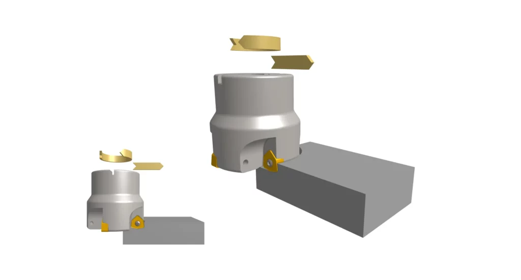
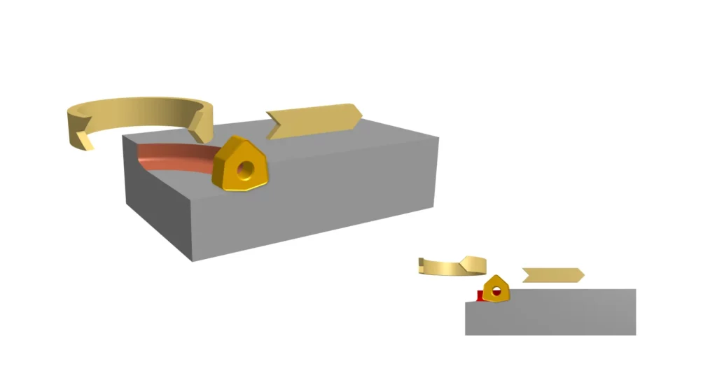
How the face milling process works
Face milling works by rotating a cutter whose axis is perpendicular to the workpiece, while feeding the tool to traverse across the surface. Multiple inserts or tool-integral cutting engage the material sequentially, creating overlapping cutting paths that deliver a flat surface, reflecting the characteristic flatness of the machining center.
The cutter usually enters the material gradually, reaches full engagement across its diameter, and exits the part after traversing the surface, usually moving along a single axis. During this process, several variables heavily influence stability and finish quality:
- Cutter diameter relative to workpiece width – larger diameter cutters typically produce flatter surfaces.
- Radial engagement, at the corners and limited peripheral cutting-edges.
- Axial depth of cut, increasing process forces.
- Insert geometry
- Tool overhang
- Workholding rigidity
- Cutter positioning relative to the centerline.
One of the most important practical considerations is cutter positioning. Positioning the cutter exactly on the workpiece centerline often creates symmetrical cutting forces that increase vibration and insert shock during entry and exit. Experienced machinists typically offset the cutter slightly off-center to reduce harmonics and improve stability.
Modern face milling generally uses climb milling rather than conventional milling because it reduces rubbing, lowers heat generation, improves insert life, and produces better surface finish.
The process is also highly dependent on rigidity. Since large-diameter face mills generate substantial radial and axial forces, insufficient spindle rigidity, weak fixturing, or long tool overhang can quickly produce chatter, waviness, or inconsistent finish.
What tools are used for face milling?
Face milling uses various dedicated cutter styles, optimized for materials, cutting loads, cut form, and surface finish requirements. Cutter geometry has a major influence on material removal rates, vibration behavior, insert (or integral edge) useful life, and achievable surface quality.
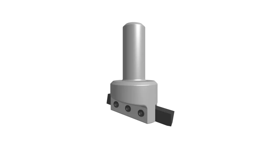
Indexable face mills and shell mills
Most industrial face milling uses indexable cutters fitted with replaceable carbide inserts. These cutters typically range from 40 mm in diameter, up to very large – over 300 mm is common.
Indexable face mills offer several advantages:
- High material removal rates
- Lower tooling cost per edge
- Fast insert replacement
- Multiple insert geometries
- Adaptability across materials
Shell mills mount directly to a spindle arbor and are commonly used on machining centers for heavy face milling operations. They provide good rigidity and support large insert counts.
Smaller face mills often use positive-rake geometries for lower power CNC machines, while heavy roughing cutters generally use negative-rake inserts, for improved strength and durability.
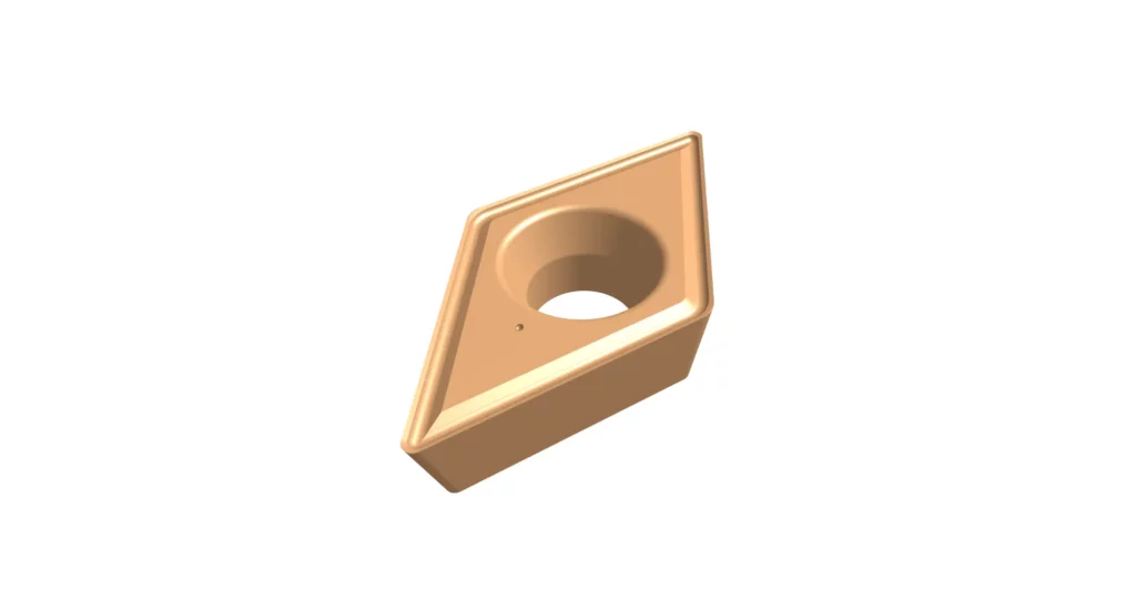
Carbide and coated inserts
Insert face milling relies heavily on carbide inserts, often with advanced coatings for added durability.
Common coatings include:
- TiN
- TiAlN
- AlTiN
- CVD multilayer coatings
- PVD coatings
The coating selection depends heavily on the material being machined.
| Material | Preferred Insert Characteristics |
|---|---|
| Aluminum | Sharp polished uncoated carbide |
| Mild steel | General-purpose coated carbide |
| Stainless steel | Tough, heat-resistant geometry |
| Titanium | Sharp positive-rake inserts, often uncoated |
| Cast iron | Wear-resistant hard coatings |
Insert geometry is equally important – positive rake angle reduces cutting forces and improves finish, but these are mechanically weaker. Negative rake inserts are stronger and better for interrupted cuts or aggressive roughing.
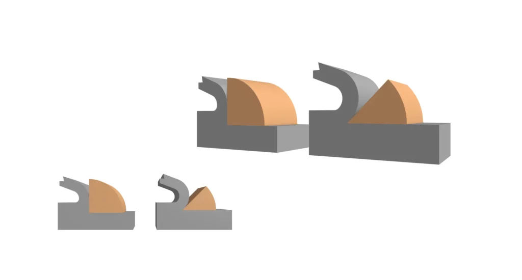
Lead-angle cutters: 45°, 90°, and round insert
Lead angle dramatically affects cutting mechanics.
45° lead angle
45° face mills are among the most common because they:
- Reduce chip thickness
- Spread cutting forces
- Improve insert life
- Reduce spindle shock
- Improve finish quality
They are especially useful in interrupted cuts and unstable setups.
90° lead angle
90° cutters generate more radial force and produce sharper shoulders. They are preferred when a true vertical wall or sharp corner transition is necessary.
They typically suffer higher insert loading and shorter useful life, particularly in interrupted cuts.
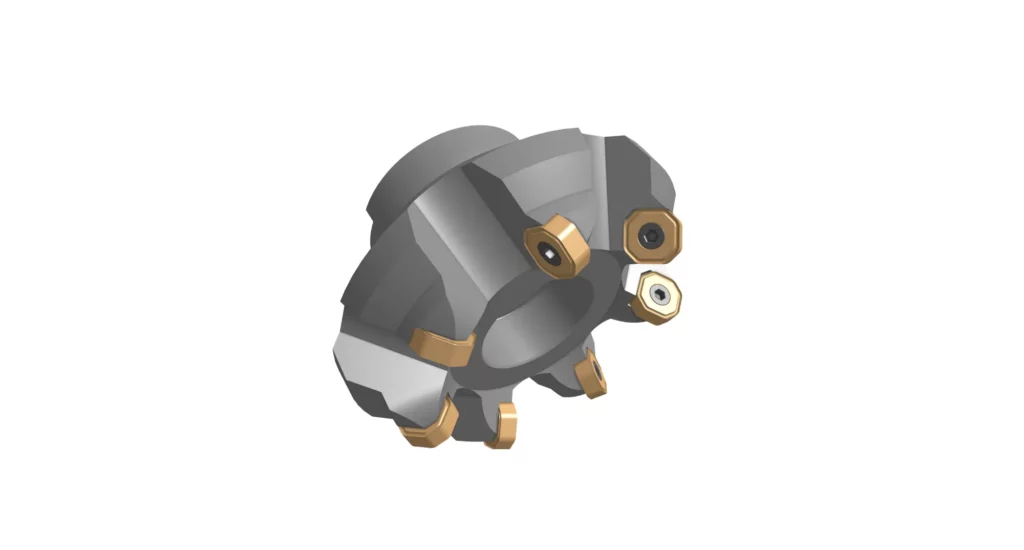
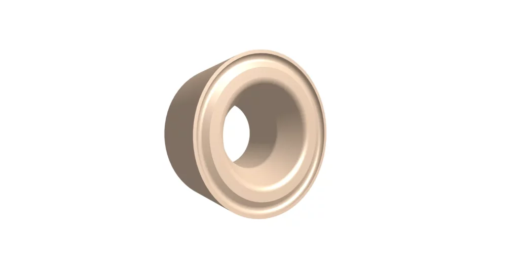
Round insert cutters
Round inserts distribute cutting loads over a large edge radius, making them ideal for:
- Heavy roughing
- High feed milling
- Difficult alloys
- Interrupted cuts
Their main limitation is lower shoulder precision and larger minimum internal radius in the resulting cuts.
Wiper inserts and their effect on surface finish
Wiper inserts dramatically improve achievable surface finish by flattening the feed marks left between adjacent insert passes.
A standard insert leaves scalloped feed marks determined by feed-per-tooth and nose radius. Wiper geometries extend the effective cutting edge, allowing higher feed rates while maintaining smoother finishes.
Typical achievable Ra values:
| Operation | Approximate Ra |
|---|---|
| Rough face milling | 3.2 to 6.3 µm |
| Standard finish pass | 1.6 to 3.2 µm |
| Wiper insert finishing | 0.4 to 1.6 µm |
Wiper inserts are especially valuable on mold plates, sealing surfaces, and precision mounting faces.
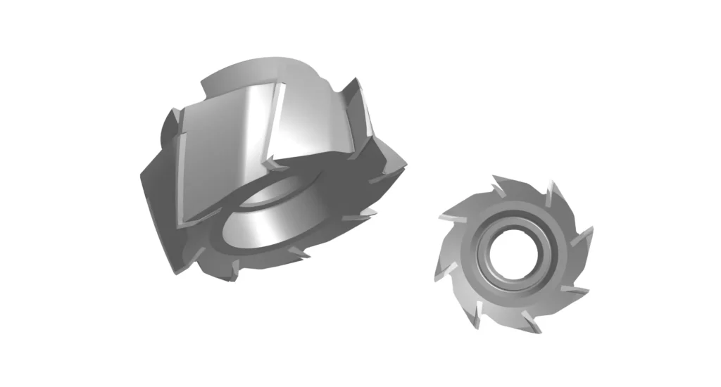
Fly cutters for light finishing
Fly cutters use a single cutting edge rotating at large diameter. Because only one insert contacts the workpiece at a time, fly cutters can produce exceptionally fine finishes under the right conditions.
Advantages:
- Very smooth finishes
- Low scallop height
- Simple geometry
Disadvantages:
- Low productivity
- Imbalance at high RPM
- Limited roughing capability
They are most commonly used for:
- Toolroom work
- Fixture plates
- Optical mounts
- Finishing passes on Aluminum
Face milling vs peripheral milling
Both face milling and peripheral milling can be used to deliver larger area, flat surfaces, but the cutting mechanics differ substantially.
In face milling:
- The spindle axis is perpendicular to the surface.
- Cutting occurs primarily on the face and corner edges.
- Large areas are machined efficiently.
- Multiple inserts share cutting load.
In peripheral milling:
- The spindle axis is parallel to the surface.
- Cutting occurs along the side edges.
- Better suited to slots, profiles, and walls.
- Surface finish direction differs.
Face milling is generally preferred for:
- Datum creation
- Large flat surfaces
- Sealing faces
- High material removal
Peripheral milling is preferred for:
- Sidewalls
- Slots
- Contours
- Precision vertical geometry
Surface texture orientation also differs. Face milling leaves overlapping circular tool marks, while peripheral milling leaves linear marks aligned with feed direction.
Face milling vs end milling and slab milling
End milling uses a smaller tool capable of plunging, profiling, slotting, and pocketing. It is more versatile but far less efficient for surfacing large flat areas.
Slab milling uses a cylindrical cutter whose axis is parallel to the surface. It is highly productive for wide horizontal surfaces but is less common on modern CNC machining centers.
Face milling occupies the middle ground:
- more efficient than end milling for surfacing
- more flexible than slab milling
- ideal for modern CNC machining centers
Feeds, speeds, and cutter engagement in face milling
The most important face milling parameters are:
- cutter diameter, relative to the workpiece size and cut depth.
- cutter positioning
- lead angle
- feed per tooth
- radial engagement
These factors heavily influence vibration (chatter), chip thickness, insert life, and surface finish.
Choosing a cutter diameter relative to the workpiece
A common guideline is selecting a cutter diameter approximately 20 to 50% larger than the workpiece width.
If the cutter is too small:
- engagement becomes unstable
- insert loading increases
- finish consistency decreases
If the cutter is excessively large:
- machine power demand rises
- machine rigidity requirements increase considerably (vibration risk increases)
Off-centre cutter positioning to reduce vibration
Positioning the cutter moderately off-center is a technique that reduces harmonic oscillations/loading.
Centered engagement creates symmetrical entry and exit forces, increasing vibration risk.
Offsetting the cutter:
- smooths insert engagement
- reduces shock loading
- improves stability
- improves finish consistency
This becomes particularly influential in maintaining stability/quality during interrupted cuts.
Chip thinning and the role of lead angle
Lead angle affects actual chip thickness.
A 45° lead angle spreads the cut over a longer edge length, effectively thinning the chip. This allows higher feed rates without excessively increasing insert loading.
This is one reason 45° cutters often outperform 90° cutters in:
- unstable setups
- interrupted cuts
- high-feed applications
Chip thinning is frequently misunderstood because machinists may increase feed-per-tooth substantially while maintaining manageable cutting loads.
Surface finish in face milling
Surface finish in face milling depends on:
- insert geometry
- nose radius
- feed rate
- rigidity
- cutter positioning
- machine stability
- use of wiper inserts
Typical achievable finishes include:
| Process | Typical Ra |
|---|---|
| Roughing | 3.2 to 6.3 µm |
| Standard finishing | 1.6 to 3.2 µm |
| Wiper finishing | 0.4 to 1.6 µm |
| Fly cutting | ~0.4 µm |
Flatness and Ra are not the same thing. A surface may exhibit good roughness but poor flatness (waviness) if the setup lacks rigidity or thermal stability.
Excessively tight Ra callouts are also common design specification errors. Many mating surfaces function perfectly well at 1.6 to 3.2 µm Ra, while unnecessarily specifying 0.4 µm may require secondary grinding or polishing.
What are the applications of face milling?
Face milling appears throughout CNC machining workflows, from initial stock preparation in squaring, surface cleaning and datum-face creation, to final finishing operations.
Squaring stock and setting the Z datum
This is usually the first operation on raw material.
The face mill:
- levels the stock
- removes saw-cut irregularity
- creates the primary reference plane
Every downstream operation builds off this datum, so it is a critical indicator of overall quality that the face milling operations are precise.
Roughing large flat surfaces
Face milling offers extremely high material removal rates on:
- fixture plates
- machine bases
- mold plates
- large housings
Large-diameter cutters with multiple inserts make the process high-throughput, with potential for extreme material removal rates.
Finishing mating faces, sealing surfaces, and mold plates
Fine face milling is widely used for:
- gasket surfaces
- hydraulic sealing faces
- mold bases
- robotic mounting interfaces
- precision assembly surfaces
These operations often use finishing inserts or wiper geometries that deliver improved surface quality, at the expense of throughput.
Face milling by material
Different materials require significantly divergent face milling strategies.
Aluminium (6061, 7075)
Aluminum allows very high cutting speeds and aggressive feed rates.
Key considerations:
- sharp polished inserts
- high spindle speed
- chip evacuation
- built-up edge prevention
Failure mode:
- material welding to inserts, causing rough and over-depth cutting and very poor surface quality
Steels (mild, medium carbon, alloy, stainless)
Steel requires more conservative speeds and tougher insert geometries.
Stainless steels especially generate heat, through a strong tendency towards work hardening in higher Nickel or Chromium content alloys.
Key considerations:
- coated carbide inserts
- stable engagement
- coolant control
- avoiding rubbing
Failure mode:
- heat-induced insert wear
Titanium and nickel alloys
Titanium and Nickel alloys generate high heat concentration at the cutting edge and require aggressive cooling strategies and moderated cut depth/feed rates.
Key considerations:
- lower cutting speeds
- sharp positive-rake inserts
- rigid setups
- controlled engagement
Failure mode:
- catastrophic insert failure from heat concentration
Cast Iron and engineering plastics
Cast Iron is relatively free machining, but produces abrasive chips containing carbides that degrade tools rapidly.
Failure mode:
- abrasive edge wear
Engineering plastics require sharp tooling and lower cutting forces to avoid:
- melting
- deformation
- burr formation
Common face milling defects and pitfalls
Most face milling problems originate from:
- poor cutter positioning
- unstable workholding
- incorrect insert geometry
- insufficient spindle rigidity
Common defects include:
| Defect | Cause |
|---|---|
| Chatter marks | Vibration and poor rigidity |
| Uneven finish | Insert height mismatch |
| Thermal distortion | Excessive heat |
| Poor flatness | Weak fixturing |
| Insert chipping | Interrupted cuts |
| Built-up edge | Incorrect insert geometry |
Interrupted cuts over holes or slots are particularly problematic, because inserts repeatedly enter and exit the material, increasing shock loading and risk of insert-chipping.
DFM for face milled surfaces
Face milling is straightforward when the geometry is designed for it – and expensive when it is not.
The biggest DFM mistakes include:
- unrealistic flatness requirements
- excessive surface finish requirements
- interrupted cuts
- insufficient finishing allowance
- poor workholding geometry
Designing surfaces that are easy to face mill
Large uninterrupted surfaces machine more consistently and with lower vibration/tool wear/cutter loading than interrupted faces with holes and slots.
Designers should:
- minimize interruptions, and instruct altered cutter parameters where they are required.
- maintain rigidity by not associating thinned and flexible zones with cutter interruption (incomplete surfaces) risk.
- allow stable fixturing access
Specifying realistic flatness and surface finish callouts
Many drawings specify grinding-level tolerances unnecessarily.
Typical face milling capabilities:
- standard flatness: ~0.05 to 0.10 mm
- precision setup: significantly tighter with controlled conditions
Excessively tight tolerances increase:
- machining time
- inspection cost
- scrap risk
without functional benefit.
Allowing enough stock for roughing and finishing passes
A proper finishing pass requires remaining stock.
If roughing removes all allowance:
- insert pressure varies
- finish consistency suffers
- flatness degrades
A controlled finishing allowance improves dimensional stability and finish predictability. While these are CNC programming issues to be addressed at production, parts created from hybrid processes such as forging, casting etc must be designed with sufficient material to enable effective machining processes.
How JIga supports face milling work
Face milling is usually the first operation performed on a machined part, which means early machining of this stage is foundational in influencing the success of every later operation. Questions such as:
- which surfaces need finish passes,
- what Ra actually matters functionally,
- whether interrupted cuts are acceptable,
- and how flatness should be inspected
are often best resolved through direct communication with the machinist rather than requiring their inference from a drawing. Understanding intent can be hard to derive from a component drawing.
This is particularly important when parts involve:
- sealing surfaces,
- thin-wall structures,
- large plate geometries,
- difficult alloys,
- or tight flatness callouts.
Jiga acts as a concierge rather than a manufacturing intermediary, putting the designer and the machinist in direct contact and standing to the side of this relationship, to offer support where it is needed.
Direct communication with the machinist before the first cut
Face milling parameters often depend on:
- spindle rigidity,
- available cutter sizes,
- insert systems,
- workholding strategy,
- and machine horsepower.
Direct machinist communication helps prevent unnecessary tolerances and avoidable process risk before machining begins. Enabling and facilitating this is perhaps the greatest strength of the Jiga process.
Inspection capability for flatness and surface finish
Not all suppliers inspect flatness or Ra the same way.
Critical parts may require:
- CMM inspection
- granite surface verification
- profilometer measurements
- controlled environmental inspection
Understanding this before production reduces downstream quality disputes.
Matching parts to shops with the right spindle capability
Large-diameter face milling places significant demands on:
- spindle torque
- machine rigidity
- insert systems
- fixturing stability
A shop optimized for small precision work will likely not be ideal for heavy face milling of large components, while a high-power horizontal machining center will handle the operation more efficiently.
Matching the work to the correct machine platform matters substantially for both cost and quality.
Conclusion
Face milling is a foundational operation in CNC machining, because it establishes the reference surface that every later feature depends on. While not glamorous, it is key to a quality outcome.
Successful face milling depends on three core factors:
- selecting the correct cutter geometry for the material and operation,
- controlling cutter engagement and positioning to maintain stable cutting conditions,
- and applying realistic DFM principles to flatness and surface finish requirements.
When face milling is executed correctly, subsequent operations inherit a stable, repeatable datum surface that enables follow-on precision to be maintained. When it is poorly planned or poorly specified, the resulting errors propagate throughout the entire machining process.
Frequently Asked Questions
Can you face mill with an end mill if you don't have a dedicated face mill?
Yes, especially on smaller parts or low-power machines. However, end mills are much less efficient for surfacing large areas because they have fewer cutting edges, tend to be smaller diameter, and they are suited to lower material removal rates. Dedicated face mills produce flatter surfaces more efficiently and with better finish consistency.
How tight a flatness tolerance can a face-milled surface actually hold?
Typical face milling operations may achieve roughly 0.05 to 0.10 mm flatness under typical shop conditions. Much tighter tolerances are possible with rigid setups, thermal control, precision machines, and finishing passes, but eventually grinding or lapping may become more economical.
Do I need a drawing for a face-milled part, or is a STEP file enough?
A STEP file is often sufficient for geometry, but critical information such as:
- datum structure,
- flatness tolerances,
- Ra requirements,
- inspection notes,
- and sealing-surface requirements
should still appear on a carefully annotated and standards-compliant 2D drawing.