
Prototype production lead time is the total elapsed time from finalization of the current design stage to the receipt of a physical part for evaluation. Unlike mass-production lead time, prototyping operates under low volume, high iteration pressure, and often very limited tolerance for process overhead. Every day saved in this phase accelerates design-validation, lowers costs, and strengthens competitive advantage.
Reducing prototype production lead times requires a structured approach across four pillars: optimizing design for manufacturability (DFM), selecting the most appropriate rapid manufacturing technology, managing supply and logistics efficiently, and streamlining internal workflows. This article is a practical guide for engineers and product designers looking to compress iteration cycles without compromising functional evaluation or design intent.


Key takeaways
- Prototype production lead time is the total time from design-stage sign-off to receiving a physical part, and compressing it is one of the highest-leverage actions an engineering team can take.
- Early-stage DFM eliminates the back-and-forth that causes most downstream delays.
- Choosing the right rapid manufacturing technology – 3D printing, CNC machining, or rapid tooling – directly determines prototype turnaround speed.
- Careful supplier selection and direct communication often save weeks compared to black-box platforms.
- Parallel execution of design, procurement, and approval tasks removes avoidable waiting time from every iteration cycle.
What is prototype production lead time, and why does it matter?
Prototype production lead time begins once the final design is approved and ends when the first physical prototype arrives for evaluation. This metric differs from production lead time because prototyping prioritises speed and learning over volume and process optimisation for cost.
Long lead times during the prototyping phase delay validation, increase costs, and impede iterative development.
For example, a week’s prototyping sluggishness due to purchase decisions, logistics issues etc per iteration can multiply across multiple design revisions, adding months to a development program. Reducing prototype production lead time compresses the feedback loop, enabling engineers to identify issues, test features, and make informed design decisions faster.
Under ideal conditions, a sequence of; design today; prototype tonight; evaluate tomorrow delivers the optimum pace of development and micro-iteration.
For engineers sourcing parts, understanding where time is lost – whether in design iteration, process choice, supplier delays, or internal approvals – enables targeted interventions. The strategies outlined below focus on high-leverage areas where small changes can yield outsized reductions in lead time.
Optimize Design for Manufacturability (DFM) before sending RFQs
DFM is the most powerful lever for reducing prototype production lead time. Engineers who skip DFM analysis risk creating iterative delays that compound across every cycle. Rather than framing DFM as a quality control measure, consider it a speed and lead-time strategy.

Simplify geometry to reduce CNC operations
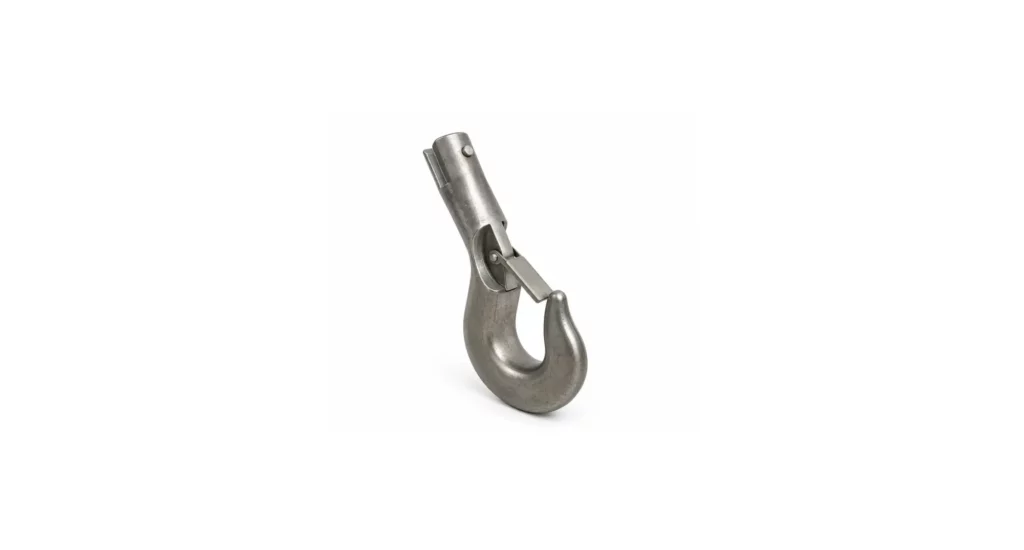
Complex geometries increase machining time and the likelihood of rework. By simplifying features – reducing deep pockets, fillets, and intricate contours – designers can reduce CNC cycle times by 20 to 40% per part. Using a ‘design for prototype’ approach can yield great benefits. For instance, replacing a complex internal rib network with fewer structural supports may shave hours off machining without compromising prototype function.
Focus the prototype design on the details requiring evaluation and simplifying or removing high-confidence features can yield significant timeline benefits.


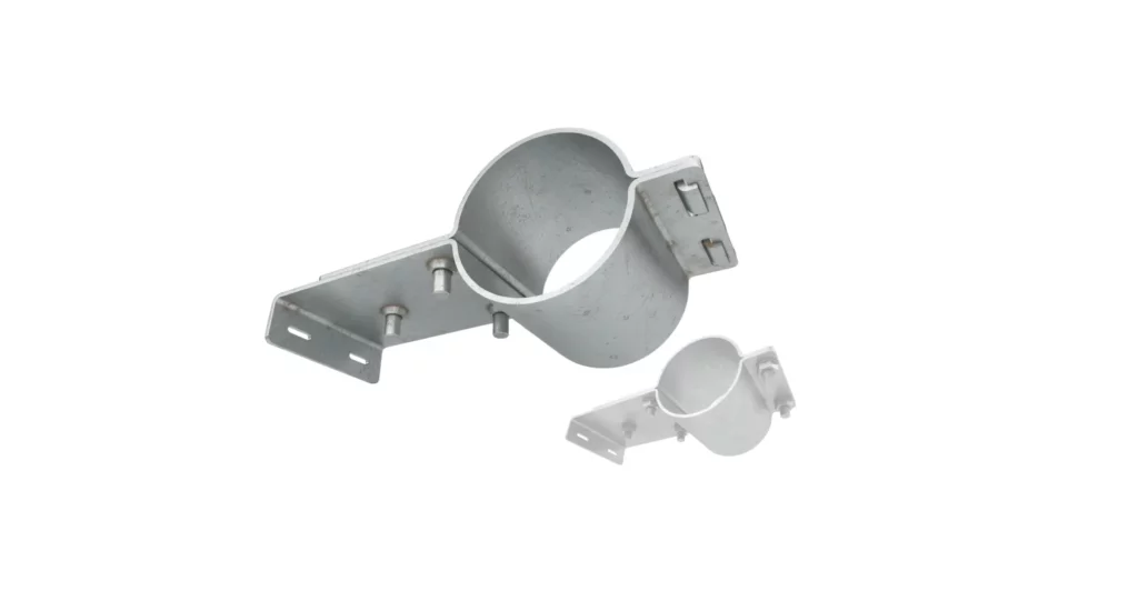
The same part with all adhesion features removed is an equally valid fit and initial blade positioning assessment prototype. The features removed result in a better than 50% reduction in on-machine time, as well as significantly reduced setup/programming time.
Relax tolerances on non-critical features
Not every dimension requires tight tolerances. Limiting ±0.01 mm (or coarser) tolerances to functional features avoids unnecessary machining complexity and inspection. In practice, relaxing tolerances on secondary holes or minor surface finishes can reduce lead time by several days without influencing iteration-learning, especially in CNC or injection-moulded prototypes.
Use standard and off-the-shelf components
Integrating standard fasteners, bushings, or bearings eliminates sourcing delays. For example, specifying a widely available M3 screw or a COTS bearing rather than custom equivalents reduces waiting time for parts and avoids additional supplier quotes. These choices can save several days per iteration, without influencing prototype utility.
Use simulation software before manufacturing
Digital verification of mechanical, thermal, and structural performance reduces the chance of physical re-spins. Running a quick finite element analysis or kinematic simulation before fabrication can prevent wasted cycles. Engineers report that proactive simulation can save weeks in stage-evaluation on multi-iteration prototypes.
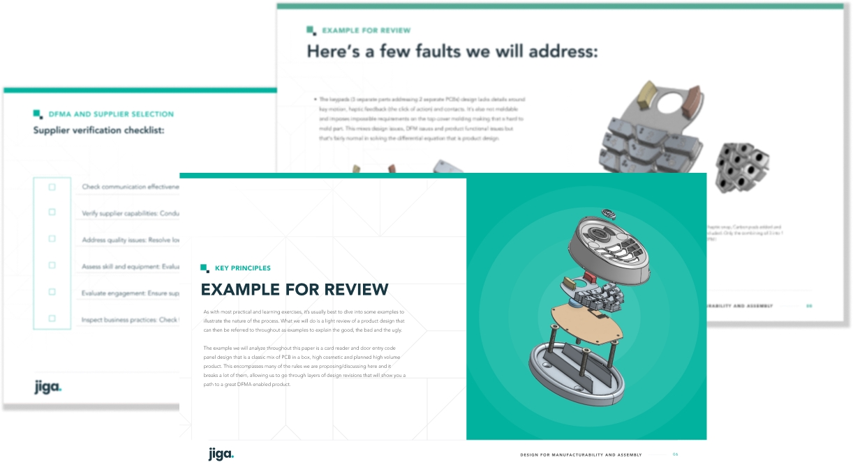
Get DFM feedback directly from your manufacturer
Platforms like Jiga allow engineers to solicit DFM feedback before sending designs for quotation. Direct dialogue with a manufacturing specialist identifies potential bottlenecks, material limitations, and process constraints early. By resolving these issues upfront, lead time lost to back-and-forth emails and RFQ revisions can be reduced by 30 to 50%.
Choose the right rapid manufacturing technology for your prototype
Selecting the appropriate manufacturing process is critical to minimising prototype production lead time. Each technology has strengths and limitations, selection of which is driven by functional requirements in the evaluation of each generation of prototype.
3D printing for form, fit, and rapid iteration
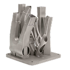
Additive manufacturing excels at rapid iteration and visual or conceptual prototypes. Typical turnaround for small parts ranges from hours to a few days, depending on supplier agility/geography, print size and post-processing needs. Materials include PLA, ABS, nylon, various metals, and engineering-grade resins for functional testing. Key time-saving tips include orienting parts to minimize supports and exploit process anisotropy, reducing layer height (in higher resolution component production) only where necessary, and batching parts together to improve build table utilization and parallel production efficiencies.
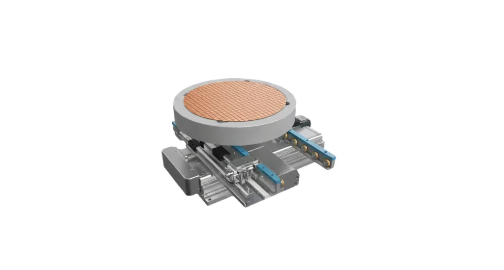
CNC machining for functional and structural prototypes
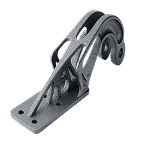
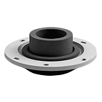
CNC machining delivers more mechanically robust prototypes with precise tolerances and more production-representative material options. Lead times vary based on material hardness, availability (for exotic options) and complexity; Aluminium or plastics can be machined in 1-2 days, while stainless steel or hardened alloys may take 7 to 10 days. Simplified features, fewer setups, and communication with machinists on tolerances and workholding reduce iteration delays. Early CNC process decisions often cut several days off total prototype lead time.
Rapid tooling for low-volume moulded prototypes
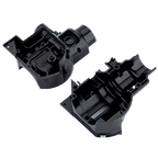
When functional thermoplastic prototypes in production-representative materials and properties are imperative, rapid tooling can be appropriate. This enables injection-moulded parts at small volumes (down to a few pieces). Lead times for Aluminium or silicone molds typically range from 1 to 3 weeks. Choosing rapid tooling early ensures that design iterations remain compatible with production tooling and avoids waiting on full-scale production tools – but the schedule and cost implications can be significant, so this option is not necessarily an easy path.
Manage suppliers and logistics to remove sourcing delays
Poor supplier management is one of the most underestimated causes of prototype production lead time delays. Engineers often focus on machining or printing time but overlook quotation cycles, shipping, and communication inefficiencies.
Communicate directly with the manufacturer, not a middleman
Direct communication eliminates delays inherent in intermediary platforms or agents. Questions about tolerances, material availability, or setup requirements can be resolved in hours rather than days. On the Jiga platform, engineers can message suppliers directly, reducing response time sluggishness to same-day guidance, by removing comms chain participants.
Compare multiple quotes without multiplying admin
Receiving multiple quotes can create administrative overhead if handled manually. Platforms that provide side-by-side supplier comparisons, capability notes, and turnaround estimates save days of back-and-forth while allowing informed selection. Jiga enables this in a frictionless way that optimizes outcomes AND timelines.
Communicate material and quantity needs early
Providing clear specifications – including material type, heat treatment state, and batch quantity – prevents hang-ups. Early clarity can save several days by eliminating follow-up questions, mistaken executions, or partial quotations.
Build preferred supplier relationships
Establishing trusted supplier relationships ensures faster responses, prioritization, and pre-validated capability. Repeat engagement reduces risk of unexpected delays and improves reliability across iterations.
A repeat client is typically a priority client, for most jobbing type suppliers.
Streamline internal workflow to remove avoidable waiting time
Internal bottlenecks often go unnoticed but have real impact on prototype production lead time. Sequential task execution, bureaucratic approvals, and poorly digitized documentation create avoidable waiting. Jiga will help you evade these pitfalls.
Run design and procurement steps in parallel
Whenever possible, initiate supplier quotes while final design tweaks are ongoing. For instance, ordering preliminary CNC setups while final tolerances are confirmed can save several days per iteration.
Use value stream mapping to identify bottlenecks
Visualising the prototype workflow highlights unnecessary waiting points. Common bottlenecks include multi-layered internal approval for minor design changes and delayed material ordering.
In many cases, the approval to spend sits with a non-engineering control point. Spend the time to educate your internal process node personnel in the value proposition that prototypes represent – and in the critical nature of the process selection. Accountants will always understand overall process cost-benefit, where massive process cost differentials between prototype options may be choke issues, as standalone analysis points.
Be systematic with work instructions and RFQ documentation
Maintaining digital design file version control, file formats/resolutions, checklists, and automated RFQs prevents repeated manual documentation and file suitability errors. Assertive process management and integrity often reduce administrative delays by 20 to 30%, and avoid repeat/redundant cycles – translating to potential days saved per iteration cycle.
How much time can these strategies save?
| Strategy | Estimated Time Saved | Notes |
|---|---|---|
| Early DFM | 3–10 days | Depends on design complexity |
| Direct supplier communication | 1–2 weeks | Avoids back-and-forth |
| Technology selection (3D/CNC/Rapid Tooling) | 2–7 days | Based on process choice |
| Parallel internal workflow | 2–5 days | Removes sequential bottlenecks |
| Digital documentation | 1–2 days | Reduces admin and errors |
Cumulatively, an engineer applying these strategies can reduce prototype production lead times by 30 to 50%, turning what might be weeks per iteration into days, while improving stage-evaluation outcomes. Jiga makes implementation straightforward by combining direct DFM feedback, verified supplier capability, and integrated quoting.
How to choose the right supplier to boost prototype lead times
Supplier selection is a strategic decision, particularly so for prototypes. A shop that excels at low-cost production may not be suited for tight-tolerance or exotic-material prototypes. Mistaken choices here can add weeks to lead time due to re-spins or quality failures.
Key considerations:
- Capability verification: Ensure the supplier has prior experience with the material, tolerance, and process required.
- Direct communication: Confirm setups, tooling, and post-processing strategies with engineers rather than relying on generic platform instructions.
- Location and logistics: Domestic suppliers can save weeks in shipping compared to international partners.
- Flexibility: Prototype iterations demand adaptability; suppliers must handle last-minute design changes (file substitutions) without error or significant delay.
Jiga’s vetted network enables engineers to filter suppliers based on capability, lead time, and material expertise. Direct messaging and pre-validated quotes reduce uncertainty and prevent the common “quote/reject/re-spin” cycles that represent catastrophic schedule bloat in far too many cases.
Summary
Reducing prototype production lead time is a combination of smart design, technology/material selection, design modulation-to-process, supplier management, and workflow optimization. Applying DFM early, selecting the right manufacturing process, and streamlining internal and external communication can cut lead time by 50% or more.
Jiga make these strategies actionable, giving engineers direct access to verified suppliers, real-time DFM feedback, and rapid and low-friction iteration cycles. By systematically addressing the high-leverage factors, engineers can accelerate prototyping, reduce costs, and improve product development velocity.