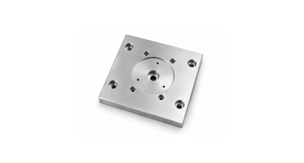

A successful prototyping outcome is one that demonstrates that the product works, as intended.
It does not validate that the part/product can be manufactured in volume.
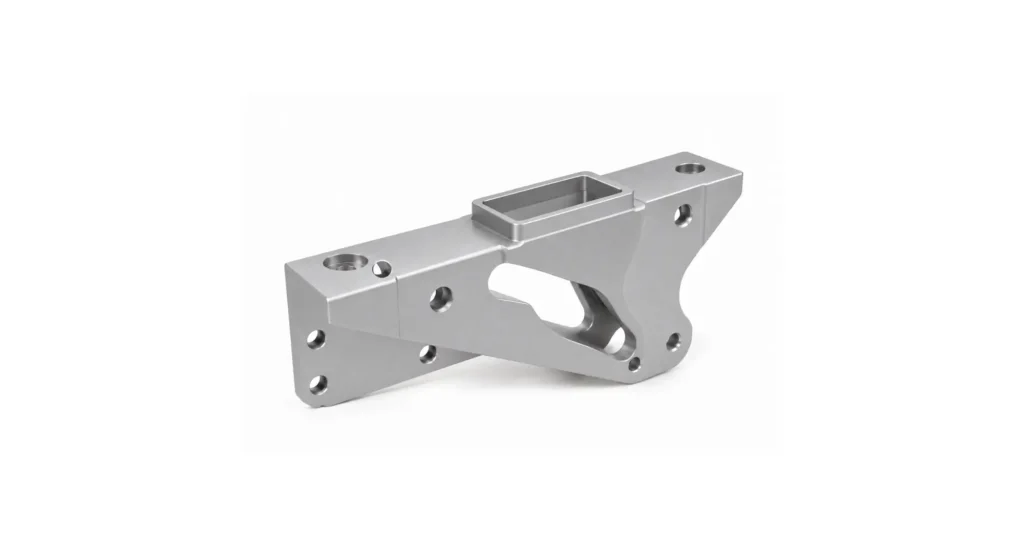
That distinction is responsible for many delayed launches. A component that performs perfectly when CNC machined from Aluminium or printed in SLS nylon can become difficult, expensive or unnecessarily complex once it enters prototype to production injection molding transition. The geometry may be correct. The function may be proven. Yet the production design can still be wrong in subtle or profound ways.
Most articles on injection molding DFM approach this transition as a checklist. Add draft angles. Make wall thickness uniform. Remove undercuts. AI assisted DFM is essentially the same.
Such recommendations are valid, but they are also simplistic and they fall short.
The real redesign begins before any DFM checklist is consulted. It begins by recognising that the move from prototype to production solves related but divergent challenges.
A prototype provides form and functionality validation.
A production component must be optimised for repeatability.
That evolution in objective drives every engineering decision that follows, from material selection to part architecture, tooling strategy and process validation. The production CAD model should inherit the prototype’s function, but not necessarily its geometry.
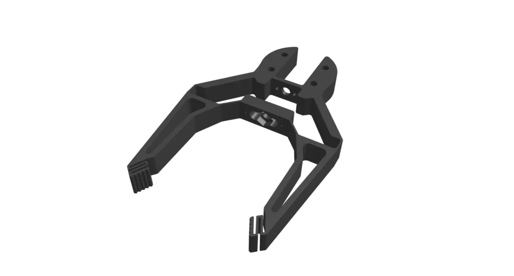
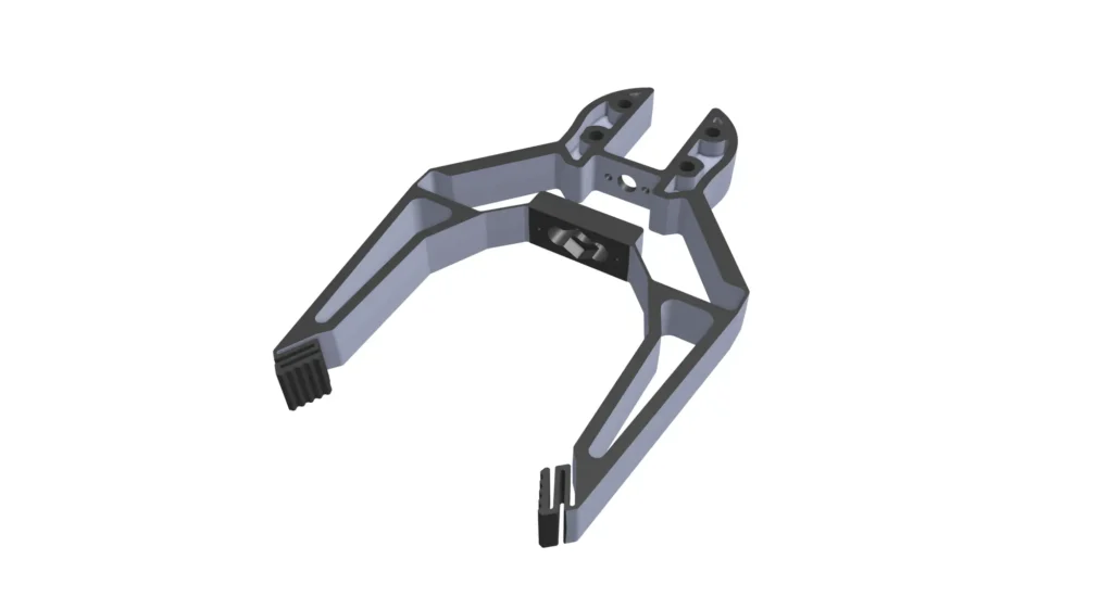
The protoype proved function, not manufacturability
Prototyping, and particularly additive manufacturing, reward free-thinking in problem/function analysis.
Injection molding rewards discipline.
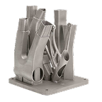
SLS allows enclosed channels, complex undercuts/galleries, variable wall sections, and complex one-piece assemblies. The process builds geometry layer by layer, not needing to respect removal of steel.
Injection molding must satisfy harsher constraints.
- Molten polymer must fill every element of the cavity.
- Air must escape.
- Heat must leave the part uniformly.
- The component must shrink predictably.
- It must eject from the mold thousands or millions of times – without damaging either the part or the tooling.
None of those constraints apply in prototyping. All of them constrain production.
This illustrates why successful prototypes cannot be viewed as production-ready CAD data. They are proofs of function that require optimisation for manufacture.
The redesign should revolve around three questions that generic DFM guides rarely address:
- Does the production material behave like the prototype material?
- Should the part architecture remain the same?
- Does the manufacturing process introduce new physical behaviour?
These questions determine how a design scales.
Material non-equivalence: The same polymer behaves differently
Perhaps the biggest misconception in product development is the assumption that material chemistry determines performance.
It does not.
Manufacturing changes material behaviour.
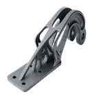
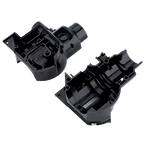
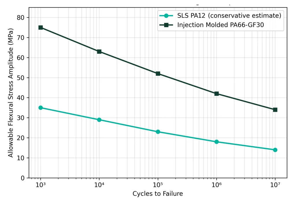
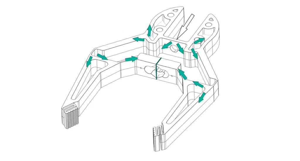
The printed PA12 gripper above, and the injection-molded, 30% GF PA66 part are chemically similar, yet their mechanical properties differ substantially. Injection molding changes the internal structure of the polymer. Additives manipulate properties. Crystallinity varies with flow and cooling effects.
Various other tasksets are required, but no existing solutions look to solve the whole puzzle in one platform – which is a considerable weakness in current offerings, as clients necessarily will use multiple tools to cover their required range.
Polymer physics changes during injection molding
When molten polymer enters a mold cavity it does not solidify uniformly.
A process known as fountain flow develops.
Material contacting the cold cavity wall freezes almost immediately, creating a thin skin layer.
Hotter material continues flowing through the centre before being forced outward toward the cavity wall.
This produces several important effects:
- molecular orientation
- fibre alignment
- crystallinity gradients
- complex residual stress
- directional shrinkage
None of these are paralleled within SLS or machined parts.
The consequence is that identical CAD geometry results in divergent mechanical behaviour depending on manufacturing process.
This implies that the prototype validated the product concept, not the production material.
Orientation creates anisotropic strength
Flow direction creates structure.
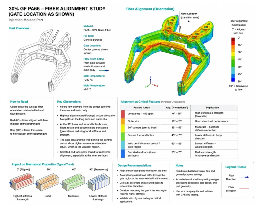
As molten polymer fills the cavity, long molecular chains and reinforcing additives lie along the direction of flow.
That orientation increases stiffness in the direction of flow. Glass-filled nylons illustrate this particularly well.
- Near the gate, glass (and polymer) align strongly with flow.
- Downstream, orientation changes to be less linear.
- In turbulent regions, alignment is lost.
- Around weld lines, alignment breaks down completely.
Printed prototypes faithfully reproduce none of these orientation effects.
Weld lines are more than cosmetic
Every complex molded part contains weld lines. They occur wherever two advancing flow fronts meet.
Many perceive them as primarily cosmetic defects. In reality they are extreme molecular discontinuities. The polymer chains arriving from opposite directions do not entangle before solidification, weakening the part at the join.
Depending on resin selection, processing conditions and gate placement, tensile strength at weld lines may decrease by up to 60%.
That influence is missing from prototypes, because additive manufacturing lacks converging flow fronts.
The engineering question therefore becomes:
“Can the weld line be moved?”
rather than
“Can the weld line be eliminated?”
Mold-flow simulation is invaluable here, as it typically predicts weld-line formation with high accuracy.
Crystallinity changes mechanical behaviour
Semi-crystalline polymers such as nylon, POM and polypropylene continue developing internal structure as they cool.
Cooling rate affects crystal growth. Crystal growth affects:
- stiffness
- toughness
- shrinkage
- chemical resistance
- dimensional stability
Rapid cooling near the cavity wall produces different crystallinity than slower cooling within thicker sections.
That difference helps explain why thick molded features often warp or shrink differently despite material constancy.
Prototype manufacturing contains none of this thermal history.
Residual stress is the hidden variable
Residual stress receives surprisingly little attention in many DFM discussions, despite influencing long-term performance.
Residual stresses develop because of differential cooling.
Consequences include:
- warpage
- environmental stress cracking
- dimensional drift
- accelerated creep
- reduced fatigue life
These effects can appear weeks or months after molding, after creep and thermal cycle release them.
The prototype cannot predict them because it never experienced bulk flow and cooling.
Product validation must include environmental testing, to assess this time dimension stability.
Shrinkage is three-dimensional
Shrinkage is often perceived as a plain and universal number.
Reality is considerably more complicated.
Production parts experience:
- linear shrinkage
- volumetric shrinkage
- differential shrinkage
- directional shrinkage
Semi-crystalline polymers typically shrink 1.5 to 2.5%, while amorphous materials such as ABS or polycarbonate generally shrink 0.4 to 0.7%.
Glass fibres further complicate behaviour by restraining shrinkage parallel to flow, while allowing amplified shrinkage across it.
Consequently, the same CAD model will typically contract differently on 3 axes.
Printed prototypes fail to predict molded dimensions, in sensitive areas.
Understanding shrinkage is not simply about scaling CAD.
It is about understanding how polymers and additives interact with geometry, gate location and cooling.
Material validation goes beyond tensile strength
Before finalizing a production resin (and additives), engineers should revisit the properties that actually determine service life.
These include:
- creep under sustained load
- UV stability
- chemical compatibility
- moisture absorption
- impact resistance
- fatigue
- UL 94 flammability performance at the intended wall thickness
These properties are frequently overlooked because prototypes are tested only for immediate function.
Production components must survive years rather than days, altering the engineering priorities considerably.
Prototype philosophy versus production philosophy
The most successful redesigns begin with a change in mindset rather than a change in CAD.
During prototyping, engineers naturally optimise for learning. The objective is to validate function as quickly as possible while minimizing iteration. Manufacturing constraints are deliberately relaxed because changing a printed prototype is fast/cheap.
Production reverses those priorities.
Once steel is cut, every design change becomes progressively high impact. Repeatability, process capability and lifecycle cost drive engineering objectives.
The transition can be summarised as follows.
| Prototype Design Philosophy | Production Design Philosophy |
|---|---|
| Validate function | Validate manufacturability |
| Minimise design time | Minimise lifecycle cost |
| Geometry freedom | Manufacturing discipline |
| Fast iteration | Stable repeatability |
| Ignore tooling | Design around tooling |
| Accept variation | Control variation |
This shift explains why successful production programs rarely use prototype geometry unchanged. The product’s function survives. The architectural detail often does not.
Part consolidation injection molding: When fewer parts become more expensive
Additive manufacturing has changed how designers think about assemblies. Part count reduction is desirable, but only as part of a wider consideration.
A printed prototype can combine multiple components into one elegant build, because there is no penalty for geometric complexity.
Injection molding follows a different economic model.
- Complexity of part drives complexity of tooling.
- Tooling complexity drives CAPEX.
- CAPEX influences every part produced during the life of the program.
Consequently, one beautifully integrated prototype may produce an expensive production mold.
The engineering question changes from:
“Can these parts become one?”
to
“Should they?”
When consolidation still creates value
Despite the tooling penalties associated with complexity, consolidation often remains the correct production strategy, when it removes more challenging/costly secondary operations.
Good candidates include integrated:
- cable clips
- locating features
- sealing grooves
- mounting bosses
- strain reliefs
- alignment tabs
Similarly, replacing threaded fasteners with molded snap fits frequently reduces assembly time, tamper, inventory and warranty issues.
Typical allowable design strain illustrates the challenge in prototyping snaps.
| Material | Typical Allowable Design Strain |
|---|---|
| Polypropylene | 6–8% |
| ABS | 2–4% |
| Glass-filled nylon | <2% |
Many prototypes are validated using printed nylon or machined acetal before production switches to glass-filled engineering polymers. If snap geometry is not redesigned, successful prototypes often become unreliable production parts because reinforced materials tolerate significantly lower elastic strain and are considerably stiffer.
Living hinges illustrate manufacturing differences
Living hinges demonstrate an important lesson.
Engineers frequently reject them because printed hinges fail after 1 or 2 cycles.
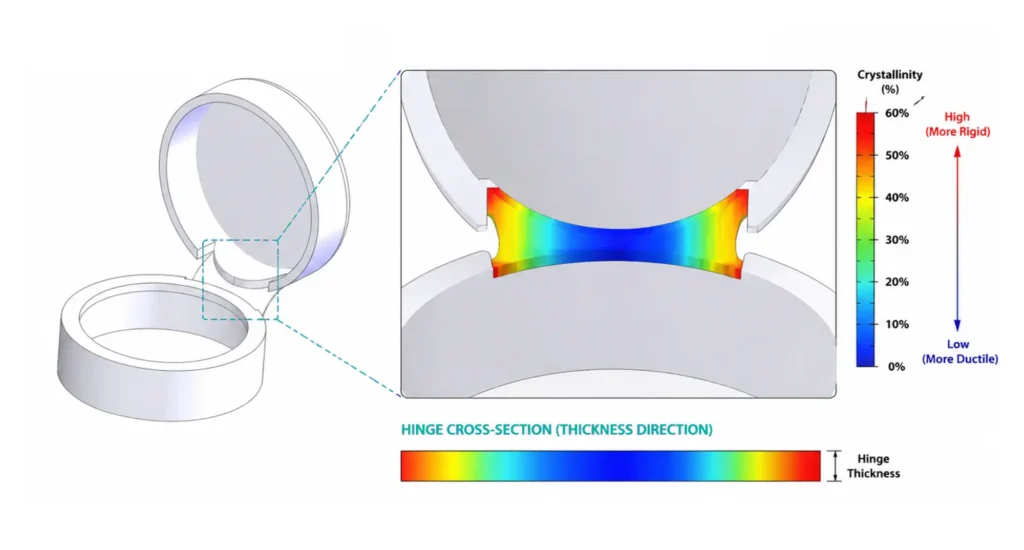
A properly designed polypropylene living hinge can survive hundreds of thousands, and sometimes millions, of cycles because injection molding creates highly oriented polymer chains across the hinge region.
The manufacturing process itself induces the material performance.
This is a reminder that prototypes validate gross functions, not finessed production behaviour.
When one part should become two
Just as additive manufacturing encourages consolidation, injection molding often discourages, or revises it.
Large monolithic prototypes commonly require:
- multiple side actions
- lifters
- collapsible cores
- deep shut-offs
- difficult cooling channels
- complicated ejection systems
Each additional mechanism increases tooling cost and maintenance, while extending cycle time.
Splitting one prototype into two straightforward molded components often reduces total program cost despite introducing a simple assembly operation.
This is where engineering economics overrule part count.
Tooling economics should drive architecture
Every tooling feature carries a financial consequence.
Each side-action typically adds approximately US$2,000 to US$10,000. They introduce additional machining, heat treatment, maintenance and wear.
More importantly, they influence every production cycle.
Additional mechanisms increase:
- mold build time
- cycle time
- maintenance frequency
- inspection complexity
- spare component inventory
Consequently, a redesign that adds one ultrasonic weld to remove four snap fits may reduce total lifecycle cost by eliminating tooling mechanisms.
The correct comparison is therefore not one part versus two parts. It is one manufacturing program versus another.
Cooling dominates production more than geometry
Most introductory DFM guides focus on wall thickness because it is easy to visualise.
Experienced mold designers usually think about cooling first.
Cooling determines:
- cycle time
- dimensional stability
- crystallinity
- residual stress
- warpage
- productivity
- manufacturing cost
A one-second reduction in cooling time affects every part produced, throughout the life of the tool.
For high-volume products, cooling efficiency often saves considerably more than reducing machining time during mold manufacture.
Good redesign therefore seeks not only uniform wall thickness but also predictable heat removal.
Large thermal mass areas, isolated thick sections and difficult-to-cool cores become redesign priorities because they extend production cycles.
Moving manufacturability decisions earlier, before steel is cut
Artificial intelligence is changing DFM, but perhaps not in the ways imagined by management.
The greatest benefit is moving the required knowledge base earlier into product development, rather than replacing product or mold designers.
Instead of waiting to fully evaluate manufacturability until tooling begins, engineers can now get real-time and insightful manufacturing feedback while design changes remain inexpensive.
That fundamentally alters the redesign workflow.
Need a second set of engineering eyes before tooling?
The biggest tooling delays usually begin long before steel is cut. Jiga connects your design with experienced manufacturing engineers who review geometry, material selection, tooling strategy and supplier capability together, helping identify production risks while changes are still inexpensive. Talk to Jiga about your production redesign before tooling begins.
What useful DFM feedback actually looks like
A valuable DFM review goes far beyond identifying draft or wall section issues.
Process-specific feedback should explain:
- preferred gate locations
- expected weld-line position
- likely sink depth
- fibre orientation
- cavity pressure distribution
- cooling balance
- predicted warpage
- shrinkage direction
- venting requirements
- packing and holding sensitivity
Most importantly, these recommendations should reflect the selected resin, machine capability, and tooling strategy rather than generic geometry rules.
Automated DFM has limits
utomated DFM systems are becoming increasingly capable.
They excel at recognising:
- missing draft
- thin features
- difficult undercuts
- unrealistic radii
- wall thickness variation
They are less capable of understanding manufacturing priorities.
An automated report cannot decide whether:
- a cosmetic blemish is acceptable
- a weld line crosses a structural feature
- cycle time should take precedence over cosmetic perfection
- a family mold is preferable to separate tools
- glass-filled nylon is commercially justified
These decisions still require close collaboration between the designer and the tooling/molding team.
The strongest workflow combines automated analysis, mold-flow simulation and practical production experience, avoiding over-reliance on any one analysis
The redesign sequence
The redesign process increasingly follows this sequence: functional prototype, production resin selection, architecture review, automated DFM analysis, mold-flow simulation, engineering review with the molder, CAD refinement, tool quotation, and steel manufacture.
This workflow represents the real value contribution of AI-assisted injection molding DFM. It does not replace engineering judgement. It allows clearer engineering decisions to be made while meaningful changes remain inexpensive.
The engineer's redesign framework
There is no universal checklist that converts a successful prototype into a successful production component, despite many such being published.
Every product presents a unique set of materials, geometries, production volumes, and commercial constraints.
There is, however, a repeatable engineering framework that consistently leads to better decisions.
Instead of asking “Is this design moldable?”, analyse the following, in sequence.
Step 1: Revalidate the material
Forget the prototype resin.
Ask whether the production resin still satisfies the product requirements.
Review:
- Long-term creep
- Impact resistance
- Fatigue performance
- Chemical compatibility
- UV stability
- Moisture absorption
- UL 94 flammability requirements
- Service temperature
- Dimensional stability
Remember that production properties depend on both resin selection and the molding process.
Step 2: Challenge the architecture
Do not assume the prototype architecture is optimal.
Ask:
- Should one part become two?
- Can two parts become one?
- Should screws become snap fits?
- Can assembly be eliminated with living hinges?
- Is tooling complexity justified by assembly savings?
- Does the architecture support future design revisions?
The objective is not minimum part count, it is minimum lifecycle cost.
Step 3: Design around manufacturing physics
Instead of reviewing CAD features individually, review the physical behaviour inside the mold.
Consider:
- Flow direction
- Gate location
- Weld-line position
- Cooling paths
- Fibre orientation
- Residual stress
- Shrinkage direction
- Ejection forces
These mechanisms ultimately determine dimensional stability and long-term product performance.
Step 4: Simulate before you commit
Simulation should answer engineering questions, not simply produce colourful images.
Before releasing tooling, confirm that mold-flow analysis has investigated:
- Fill balance
- Air traps
- Pressure requirements
- Gate freeze time
- Fibre orientation
- Differential shrinkage
- Sink risk
- Warpage
- Cooling efficiency
Where simulation highlights uncertainty, revise the CAD model rather than assuming process tuning will compensate later.
Step 5: Involve the molder early
Perhaps the simplest recommendation is also the one most often ignored. Speak directly with the engineers who will build and operate the mold.
Discuss:
- Cosmetic surfaces
- Functional dimensions
- Datum strategy
- Surface finish
- Inspection requirements
- Resin selection
- Tooling philosophy
- Expected production volume
Engineering intent should never be communicated solely through a drawing package.
The earlier these conversations occur, the less expensive the process will prove.
Production readiness checklist
Before committing to production tooling, confirm each of the following.
| Review Area | Questions to Answer |
|---|---|
| Material | Has the production resin been fully validated for service conditions rather than simply matching the prototype? |
| Architecture | Does the part count minimise total program cost rather than simply reducing assembly operations? |
| Manufacturability | Have draft, shrinkage, cooling, gate location and ejection all been reviewed together rather than independently? |
| Simulation | Has mold-flow analysis been completed using the actual production resin and expected processing conditions? |
| Tooling | Does tooling complexity reflect production volume and commercial requirements? |
| Inspection | Have critical dimensions, datums and inspection methods been agreed before tooling begins? |
| Supplier Collaboration | Have engineering discussions taken place directly with the tooling engineers rather than solely through procurement? |
If every answer is “yes,” the project is ready to move from prototype toward production with considerably lower technical risk.
If your prototype has passed functional testing but you’re unsure whether it’s ready for production, Jiga can coordinate DFM review, mold-flow feedback, supplier selection and production planning through a qualified manufacturing network.
Discuss your project with a Jiga manufacturing engineer.
Engineering standards and reference documents
A production redesign should be grounded in recognised engineering standards, rather than individual supplier preferences.
The most useful references include:
| Standard | Application |
|---|---|
| ISO 20457 | General tolerances for injection-molded plastic parts |
| ISO 294 | Preparation of molded test specimens |
| SPI Mold Finish Standards | Surface finish classification and draft implications |
| ASTM D638 | Tensile properties |
| ASTM D790 | Flexural properties |
| ASTM D256 | Izod impact testing |
| ASTM D648 | Heat deflection temperature |
| UL 94 | Flammability classification |
Material-specific design guides from resin suppliers such as BASF, DuPont, SABIC and Covestro should also be consulted when designing snap fits, living hinges or highly loaded structural features. Allowable strain and processing recommendations vary significantly between materials and supplier variants
Key takeaways
Moving from prototype to production injection molding is not a straightforward translation from one manufacturing process to another. It is an intricate redesign exercise, driven by material science, manufacturing characteristics, and production economics.
The prototype answers one primary question: does the product work? Production asks many more: can it be molded consistently, inspected efficiently, assembled economically and manufactured for years with predictable quality?
That shift in perspective explains why the most successful production programs rarely preserve prototype geometry unchanged. Instead, they preserve design intent while rethinking architecture, material selection and manufacturability. Engineers who understand polymer orientation, crystallinity, cooling, shrinkage and tooling economics make wiser design decisions from the outset, reducing the need for expensive tooling modifications later.
AI-assisted injection molding DFM is accelerating this process by moving manufacturing knowledge earlier into development. Used alongside mold-flow simulation and direct collaboration with experienced mold designers, it enables engineers to evaluate alternatives before steel is cut rather than reacting to problems after T1 samples arrive.
Ultimately, the goal is not to make a prototype moldable. It is to create a production design that delivers the same validated function with greater consistency, lower lifecycle cost and a manufacturing process capable of producing thousands, or millions, of identical components. That is the real transition from prototype to injection molding, and it is where engineering judgement creates the greatest value.
Whether you’re transitioning from SLS, CNC machining or another prototyping process, Jiga helps engineering teams redesign components for reliable, repeatable production. From DFM reviews and tooling strategy through supplier qualification, bridge production, and production launch, we work alongside your team to reduce manufacturing risk before production begins.
Frequently Asked Questions
Is injection molding DFM simply about draft angles and wall thickness?
No. Those are necessary design rules, but they address only the geometry of the part. Successful prototype to injection molding projects also reconsider material behaviour, part architecture, tooling economics and manufacturing physics before production begins.
Why doesn't my successful prototype guarantee production success?
A prototype validates function under prototype manufacturing conditions. Injection molding introduces polymer orientation, weld lines, shrinkage, crystallinity and residual stress that can significantly alter mechanical behaviour. The production design should therefore be treated as a new engineering optimisation rather than a direct copy of the prototype.
Should I always consolidate parts before injection molding?
No. Consolidation reduces assembly operations but may dramatically increase tooling complexity. Every side action, lifter or collapsible core increases mold cost and maintenance. Engineers should compare total lifecycle cost rather than simply minimising part count.
What role should AI play during redesign?
AI-assisted injection molding DFM should accelerate engineering decisions, not replace them. Automated analysis is valuable for identifying manufacturability issues early, while mold-flow simulation predicts process behaviour. Final design decisions still depend on engineering judgement and discussion with the mold manufacturer.
When should redesign begin?
Immediately after functional validation.
Waiting until tooling quotations are requested usually means manufacturing constraints are discovered after design decisions have become expensive to change. The most successful programs treat redesign as an integral stage of product development rather than a final DFM review.