
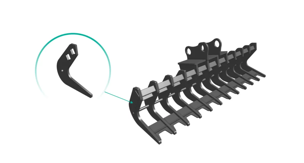
Laser cutting has become the dominant process for first-cutting of precision flat sheet metal parts. It combines high accuracy, fast setup, narrow kerf (destroyed material width at the cut), and the ability to cut complex geometries, small radii and even sharp internal corners across a huge range of materials and thicknesses. From simple structural parts to intricate electrical enclosures and aerospace components, laser cutting equips manufacturers to transform CAD designs into net-shape finished parts with zero part-specific tooling investment.
However, the difference between a laser-cut part that arrives assembly-ready, and one that arrives with burrs, distortion, poor edge quality, or dimensional issues is determined before the sheet raw material reaches the machine. File preparation, material selection, assist gas choice, feature sizing, and Design for Manufacturing (DFM) decisions all must occur upstream of production. Errors made at the CAD stage often cannot be corrected, and may not be found pre-cut, when the shop floor is a fast paced service provider.
For engineers, product designers, and procurement teams, understanding these factors is key to successful and low-waste outcomes. This guide explains how laser cutting works, how to design parts for intrinsic success, how to prepare manufacturing-ready files, and how to engage optimally with fabrication suppliers to maximise first-pass success.
Key takeaways
- Fiber lasers have largely replaced the formerly universal, now legacy CO₂ systems for most metal cutting applications due to higher cutting speeds, lower operating costs, and superior performance on reflective materials.
- Nesting efficiency in cut process setup is central to cost-efficiency, minimizing unused raw materials.
- Hole diameters should generally be at least equal to material thickness to maintain dimensional accuracy and edge quality.
- Assist gas selection directly influences edge quality, oxidation, paintability, and cost.
- DXF preparation is a manufacturing process in its own right; open loops, duplicate entities, and spline geometry frequently cause quoting and production issues.
What is sheet metal laser cutting
Sheet metal laser cutting is a thermal ablation process in which a focused, high-energy laser beam melts, burns (oxidises), or vaporises material along a programmed toolpath, to extract net-shape finished parts from flat sheet stock.
Unlike punching, stamping, or blanking operations, laser cutting requires no task-specific tooling. Geometry changes can be implemented immediately through CAD revisions, making the process ideal for prototyping, low-volume production, and dynamically customised components.
The method is characterised by:
- Narrow kerf widths
- High positional accuracy
- Minimal mechanical stress
- Complex geometry capability
- Fast setup times
- No tooling lead time
Widely available, current-technology laser systems routinely cut:
- Mild steel
- Stainless steel
- Aluminium
- Brass
- Copper
- Galvanised steel
- Precious metals
- Exotic alloys
- CFRP (carbon fiber reinforced polymer) and MMC (metal matrix composites)
Typical thickness ranges span from 0.5 mm to approximately 25 mm depending on material type, laser power, and quality requirements. Thinner materials cut easily, but require specialist handling and very low assist-gas flow. Thicker materials, up to 100mm steel, require specialist high power equipment and potentially more than one pass.
Laser cutting is particularly valuable because it works well in both prototyping and mass production, bridging between without any specific difficulties or complexity. The same machine can produce a single prototype part in the morning and hundreds of production components in the afternoon with only setup-data changes.How Laser Cutting Works
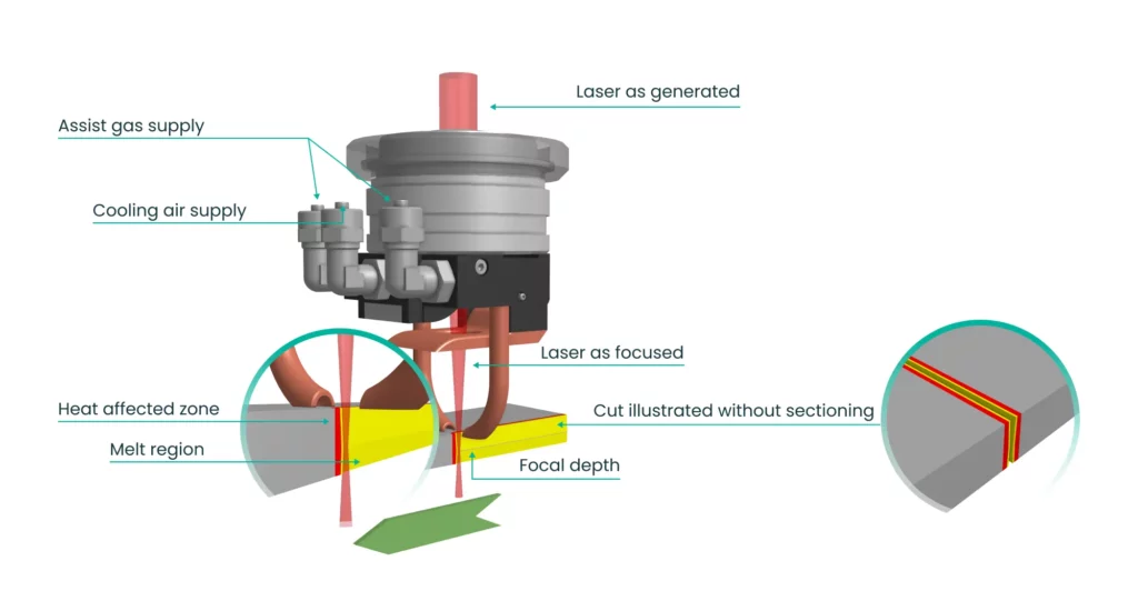
All laser cutting systems rely on the same basic operating principle. Energy generated within the laser source is focused into an extremely small spot on the workpiece. This energy rapidly raises the material temperature until melting, vaporisation, or combustion occurs. Assist gas can shield from or encourage combustion, and its flow then removes molten/oxidized/vaporized material from the kerf, allowing the cut to progress through the depth of the sheet stock.
The sequence remains broadly consistent regardless of laser type:
- Generate laser beam
- Deliver beam to cutting head (which is an area of profound differences across laser technology platforms).
- Focus beam onto material with local optics close to the cut.
- Melt, burn, or vaporise the kerf material.
- Eject ablated material by means of the flow of assist gas.
The quality of the finished cut depends on maintaining precise control of each stage.
Laser beam generation
Fabrication shops increasingly use fibre lasers, due to lower maintenance costs, a smaller equipment footprint, and a longer service life. They also benefit from improved material flexibility, due to their emission frequencies compatibility with materials that are more highly reflective of CO2 laser energy.
Within a fibre laser, energy from diode pumps excites a doped optical fibre, producing a highly concentrated beam of coherent light.
This beam is then:
- Amplified
- Directed through optical fibres to the cutter head
- Focused through precision lenses
into a cutting spot often smaller than 0.2 mm.
The resulting power density is sufficient to melt metal almost instantaneously.
Material melting and vaporisation
As the beam contacts the material, local temperature rises rapidly.
Depending on material and cutting conditions, the process may involve:
- Melting
- Vaporisation
- Oxidation-assisted combustion
The narrow beam focus allows energy to remain concentrated within a narrow zone, creating the characteristic limited kerf typical of high quality laser cutting.
Typical kerf widths include:
| Process | Typical Kerf Width |
|---|---|
| Fibre Laser | 0.10 to 0.30 mm |
| CO₂ Laser | 0.20 to 0.40 mm |
| Waterjet | 0.80 to 1.20 mm |
| Plasma | 1.50 to 3.00 mm |
Narrow kerfs improve material utilisation and enable finer feature resolution.
Assist gas functionality
Assist gas performs three critical functions, depending on the material being cut:
Material ejection
Gas jets blast molten material from the kerf, exposing the deeper cut to the laser and reducing dross buildup.
Thermal management
Assist gas helps limit excessive heat accumulation around the cut zone, reducing the depth of the HAZ (heat affected zone).
Chemical interaction
Certain gases actively influence the cutting mechanism.
Examples include:
- Nitrogen: inert, oxidation-free edges
- Oxygen: supports combustion and increases cutting speed
- Compressed air: lower-cost compromise option, for low reactivity materials
The choice of assist gas often has a large impact on edge quality, a factor that many designers may not fully realise in prototype supplier selection.
Choosing the right laser technology
For most metal fabrication applications, the choice is between fibre and CO₂ laser technology.
While both systems remain capable of producing high-quality components, fibre lasers have become the dominant platform for sheet metal processing.
Fiber laser systems
Fibre lasers offer:
- Higher energy density (and therefore cut efficiency in mm/kJ)
- Lower operating costs in power, maintenance, and higher equipment longevity
- Faster cutting speeds
- Better reflective material (particularly red reflective metals) performance
Particularly strong applications include:
- Stainless steel
- Aluminium
- Brass
- Copper
The ability to cut reflective materials reliably is one of the primary reasons fibre lasers are displacing legacy CO₂ systems.
CO₂ laser systems
CO₂ lasers remain highly relevant in some applications.
Advantages include:
- Smooth edge quality on thicker materials
- Good performance on certain non-metals, particularly organic source materials
- Established industrial infrastructure
However, higher maintenance requirements, lower component life, and lo
Laser power selection by thickness
Laser power directly influences:
- Maximum thickness
- Cutting speed
- Edge quality
- Productivity
Typical guidance:
| Power | Typical Capability |
|---|---|
| 2 to 4 kW | Thin sheet production |
| 6 to 8 kW | General fabrication |
| 10 to 15 kW | Thick-section cutting |
| 20 to 30 kW+ | High-speed production and heavy plate |
Higher power does not automatically produce better quality. Excessive power may actually increase dross formation or thermal distortion if process parameters are poorly matched.
Laser cutting vs alternative processes
Despite great capability, laser cutting is not always the optimal solution.
It is valuable to understand where waterjet, plasma cutting, punching, and stamping become more economical.
Laser vs waterject
Waterjet cutting offers:
- No heat-affected zone
- No metallurgical changes
- Superior thick-section capability
Laser cutting offers:
- Higher net cut-speed
- Lower operating cost
- Better thin-sheet productivity
Waterjet becomes attractive when:
- Material exceeds laser thickness limits
- HAZ must be eliminated
- Composite materials are involved
Laser vs plasma
Plasma cutting offers:
- Lower equipment cost
- Excellent thick-plate performance
- High productivity
Laser cutting offers:
- Better accuracy
- Narrower kerf
- Superior edge quality
- Smaller feature capability
For precision sheet metal components, laser cutting generally remains the preferred choice.
Laser vs punching
Punching becomes highly competitive when:
- Geometry repeats frequently
- Production volumes are high
- Standard punch tooling exists
Laser cutting dominates when:
- Geometry changes frequently
- Feature complexity is high
- Tooling investment is undesirable
Many fabrication shops now use combined punch-laser systems to capture advantages from both technologies.
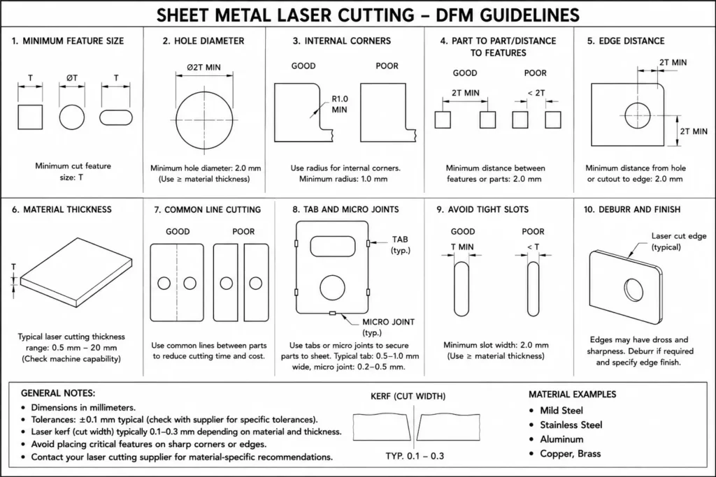
Design for manufacturing (DFM) rules
The DFM process for laser-cut sheet metal is primarily about respecting the physical limits of the thermal cutting action. Laser cutting systems are extremely accurate, but they cannot overcome geometry that violates process constraints. Features that exceed those limits will either cut poorly, distort, require secondary operations, or become impossible to manufacture consistently.
Understanding these rules before requesting a quote prevents costly DFM feedback cycles, production delays, and rejected first articles. Being aware of the differential limitations that apply according to the choice of laser technology can ease some design limitations – but great care is needed in selecting design operations that are close to the margins of possibility.
Minimum hole diameter
The most important laser-cutting rule is:
Minimum hole diameter ≥ material thickness
| Material Thickness | Recommended Minimum Hole |
|---|---|
| 1 mm | 1 mm |
| 2 mm | 2 mm |
| 3 mm | 3 mm |
| 5 mm | 5 mm |
| 10 mm | 10 mm |
Smaller holes trap heat, increase the influence of laser-profile taper, and often produce non-circular geometry regardless of machine accuracy. In particular, start points can interfere with diametral cuts when the diameter/thickness ratio becomes adverse, as there isn’t sufficient waste within the hole area to accommodate the increased HAZ that is typical from first application of the laser.
For critical holes below this threshold, drilling after laser cutting the remaining profile is often the better solution.
Minimum slot width
The same principle applies to slots. The recommended minimum slot width:
Slot Width ≥ Material Thickness
Narrow slots restrict molten material evacuation and increase dross formation.
Edge distance
Features positioned too close to sheet edges create localised heat concentration.
Recommended edge distance ≥ 1.5 × material thickness
This reduces localized distortion risk and maintains dimensional stability.
Internal corner radii
Although lasers can create sharp internal corners, thermal concentration increases significantly.
Recommended minimum internal radius ≥ material thickness
This improves edge quality and reduces stress concentration.
Thin webs and narrow bridges
Very narrow sections between adjacent cut features frequently distort during cutting.
Recommended minimum web width ≥ 1.5 × material thickness
This is particularly important in stainless steel and Aluminium.
Post-processing for laser-cut sheet metal parts
Laser cutting is frequently only the first manufacturing operation, abd post-processing steps must be allowed for as a finished-part DFM stage.
Common post-processing steps include:
For example, hole placement may affect brake forming operations, while oxide formation may affect coating adhesion.
CAD and file preparation
The laser machine cuts exactly what appears in the CAD file. It does not interpret engineering intent. A perfect design can still produce bad parts, if the supplied geometry is incorrect – and various faults may not be checked for at the cutting stage, in a busy subcontract processing facility. They SHOULD be, but assuming they WILL be is unwise!
Common file problems include:
- Open contours
- Duplicate entities
- Overlapping geometry
- Unconverted splines
- Missing layers
- Incorrect scaling
DXF best practices
Preferred formats:
- DXF
- DWG
- STEP (when converted by supplier)
Before submission:
Validate closed geometry
Every profile should form a complete loop. Even a microscopic gap can prevent successful toolpath generation, or produce a disjoint in the cutting with unexpected consequences.
Remove duplicate entities
Duplicate lines create double cuts. Symptoms of the resulting double-cutting include:
- Excessive kerf width
- Burn marks
- Distorted geometry
Convert splines to polylines
Many CAM systems struggle with native spline geometry. Converting splines to arcs or polylines improves reliability across many cutter CAM software platforms.
Maintain 1:1 scale
Never scale drawings manually before export. Geometry should always represent true dimensions, so adjustments to size should occur in the native CAD data, for reliability.
Remove uneccessary layers
Clean files reduce programming time and quoting errors.
Why open geometry causes quoting failures
Open geometry is one of the most common reasons for RFQ delays.
CAM software cannot fully and repeatably determine:
- Inside cuts
- Outside cuts
- Nesting strategy
- Lead-in placement
until profiles are fully closed.
File preparation should therefore be considered a manufacturing operation rather than a drafting exercise.
Material-specific laser cutting guidelines
Various materials behave very differently under laser energy.
Material selection affects:
- Edge quality
- Cutting speed
- Cost
- Assist gas requirements
- Post-processing requirements
Carbon steel
Carbon steel is generally the easiest metal to laser cut.
Advantages:
- High cutting speed
- Good edge quality
- Low material cost
Typical thickness:
- Up to 25 mm in a single pass, or more on higher powered systems (both CO2 and fibre laser devices)
Preferred assist gas:
- Oxygen
Benefits:
- Faster cutting
- Lower gas consumption
Trade-off:
- Oxide edge formation
This oxide layer may require removal before painting or welding.
Stainless steel
Stainless steel is one of the most common laser-cut materials.
Advantages:
- Corrosion resistance
- Excellent appearance
- Good dimensional stability
Preferred assist gas:
- Nitrogen
Benefits:
- Oxide-free edge
- Excellent cosmetic appearance
- Paint-ready surface
Trade-off:
- Higher gas consumption
- Higher operating cost
Stainless steel often justifies Nitrogen due to reduced downstream finishing requirements.
Aluminum
Aluminium reflects laser energy more readily than steel. This makes it historically more challenging for CO₂ systems, so it is now preferentially processed using fibre lasers.
Challenges:
- Reflectivity
- High thermal conductivity
- Potential edge roughness
Preferred gas:
- Nitrogen
Applications:
- Electronics enclosures
- Aerospace brackets
- Thermal management components
Copper and brass
Copper and brass are among the most reflective engineering metals. Fibre lasers handle these materials more effectively, as the metals are less reflective at the typical frequency range of fiber lasers.
Typical applications:
- Busbars
- Electrical contacts
- Heat transfer components
- RF shielding
Nitrogen is generally preferred, to minimise oxidation.
Assist gas selection
Assist gas is not merely a process parameter. It directly determines:
- Edge quality
- Oxidation level
- Productivity
- Post-processing requirements
Nitrogen applications
Nitrogen is inert. This excludes atmosphere and prevents oxidation during cutting.
Best for:
- Stainless steel
- Aluminium
- Decorative components
- Powder-coated parts
Benefits:
- Bright edge finish
- Excellent corrosion resistance
- Paint-ready surfaces
Trade-off:
- Higher operating cost
- Greater gas consumption
Oxygen applications
Oxygen promotes exothermic combustion, giving better results for some metals.
Benefits:
- Faster cutting speeds
- Improved thick steel capability
Best for:
- Carbon steel
- Heavy-gauge fabrication
Trade-off:
- Oxidised edge
- Potential need for edge preparation before coating
Air cutting
Compressed air provides a lower-cost compromise.
Benefits:
- Low operating cost
- Reduced gas consumption
Applications:
- General industrial parts
- Non-cosmetic components
- Internal structural parts
Trade-off:
- Reduced edge quality
- More oxidation than nitrogen
Laser cutting tolerances
Laser cutting is capable of excellent dimensional accuracy, but tolerances vary according to:
- Material
- Thickness
- Feature geometry
- Machine condition
Typical values:
| Feature | Typical Tolerance |
|---|---|
| External Profiles | ±0.10 mm |
| Internal Features | ±0.10–0.15 mm |
| Hole Diameter | ±0.10–0.20 mm |
| Feature Position | ±0.10 mm |
Engineers should avoid over-specifying tolerances, as these can significantly increase part costs for no benefit.
For example:
- ±0.10 mm is generally achievable.
- ±0.025 mm will typically require secondary machining, more than doubling the part cost in most cases.
Understanding where laser cutting ends and machining begins is an important DFM consideration.
Heat-affected zone (HAZ)
Typical HAZ values:
| Material | Thin Sheet | Thick Section |
|---|---|---|
| Mild Steel | 0.05–0.20 mm | 0.20–0.50 mm |
| Stainless Steel | 0.05–0.15 mm | 0.15–0.40 mm |
| Aluminium | Minimal | 0.10–0.30 mm |
These values vary depending on power, speed, and assist gas.
Laser cutting defects and troubleshooting
Most laser-cut quality issues originate from a small number of root causes. Understanding these simplifies supplier communication and eases (or obviates) corrective actions.
Burr formation
Symptoms:
- Sharp edges
- Excess material at cut edge
Causes:
- Unsuitable focus depth
- Excessive feed speed
- Worn/dirty optics allowing irregular spot formation
- Insufficient assist gas pressure
Excessive dross
Symptoms:
- Adhered molten material, making a blurred and ragged underside edge and even rejoined kerf in places
Causes:
- Poor parameter selection
- Gas flow issues
Tapered holes
Symptoms:
- Hole diameter larger on one side
Causes:
- Material thickness relative to hole size
- Focal depth poorly set
- Excessive heat concentration
Distortion and warping
Symptoms:
- Flatness loss
- Twisting
Causes:
- Heat accumulation due to poor layout
- Thin unsupported section
- Poor nesting strategy
Rough edge finish
Symptoms:
- Visible striations
- Inconsistent edge texture
Causes:
- Incorrect cutting speed
- Poor gas quality
- Improper focus settings
Best practices for clean laser-cut parts
Successful laser-cut projects begin before the RFQ is submitted.
Follow these guidelines:
- Always specify material and thickness together.
- Validate DXF geometry before submission.
- Apply minimum hole and slot sizing rules, making safety allowance where possible.
- Review edge spacing against material thickness (in design and CAM layout).
- Specify whether as-cut edges are acceptable.
- Define deburring requirements.
- Confirm assist gas requirements.
- Request first-article inspection for new designs.
- Discuss nesting strategy for material-intensive projects.
- Review DFM feedback before releasing production quantities.
The most successful projects involve direct communication with the fabricator early in the process. Many costly problems can be eliminated with a well performed DFM review, before cutting begins.
Understanding laser cutting costs
Laser cutting costs consist of more than machine time.
Primary cost drivers include:
- Material cost
- Material utilisation
- Cutting time
- Assist gas consumption
- Programming
- Setup
- Deburring
- Secondary operations
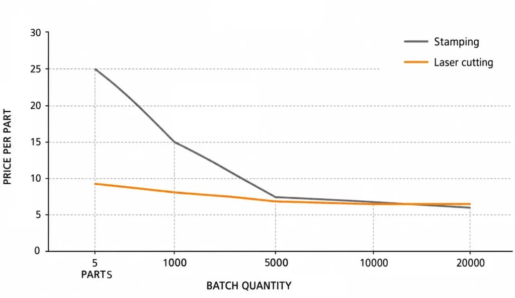
For many parts, material utilisation affects cost more than machine time. Efficient nesting can reduce waste dramatically.
Likewise, Nitrogen-assisted stainless steel cutting may carry a higher machine cost but reduce finishing and coating costs downstream, for net cost-benefit.
Automated quoting systems are useful for straightforward geometries, but experienced fabricators often identify opportunities to reduce cost through improved nesting, revised feature sizing, or alternative material selection.
This is one reason human-reviewed quotations frequently produce better outcomes than purely automated systems.
Conclusion
Sheet metal laser cutting is the primary choice for flat cut parts. It is the most versatile and efficient manufacturing process available for these components, by a wide margin. Fibre lasers deliver exceptional accuracy, fast production speeds, and broad material compatibility across industries ranging from electronics and industrial equipment to aerospace and transportation.
However, a successful outcome in a project depends more on design and file preparation than it does on machine capability. Correctly sized features, validated DXF geometry, appropriate material selection, and informed assist gas choices have a greater influence on part quality than many engineers realise. The most reliable path to first-article success is early communication with the fabricator, allowing DFM issues to be identified before material is cut.
Frequently Asked Questions
Does laser cutting affect material properties near the cut edge?
Yes. Laser cutting creates a heat-affected zone, although modern fibre lasers typically produce relatively small HAZ regions compared with many thermal cutting processes.
What file formats do fabricators accept beyond DXF?
Common formats include DWG, STEP, IGES, Parasolid, SolidWorks files, and native CAD formats depending on supplier capabilities.
Why do laser-cut parts sometimes arrive with distortion or warping?
Warping is usually caused by heat concentration, poor nesting, inadequate support, thin sections, or geometry that violates DFM guidelines.
Which DFM change reduces Does laser cutting work on sheet metal that has surface coatings or galvanising?cost most?
Yes, but coated materials may require adjusted cutting parameters. Galvanised steel can produce additional fumes and edge contamination, making supplier guidance particularly important.