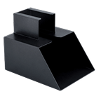
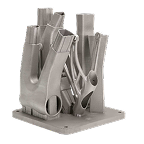
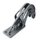
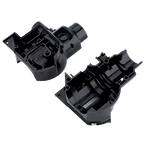
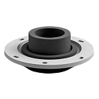

Sheet metal stamping is the cold-forming manufacturing method that transforms flat metal sheet, blanks, or coils into precise two and three-dimensional components, using pressing, turret punching and custom-designed cutting/forming dies. It is one of the most effective and repeatable production methods for high-volume parts, universally applied across automotive, aerospace, electronics, medical devices, and consumer products.
Successful stamping programs depend on three interrelated factors: robust die design, stamping-aware part design, and realistic tolerance specification. When these elements are aligned early, stamping delivers exceptional part consistency, low per-unit cost, and long-term production stability. This guide provides engineers and procurement decision-makers with a practical, process-level understanding of stamping, from die selection to tolerances and supplier sourcing.

Key takeaways
- The range of sheet metal stamping processes form flat metal stock into finished components, using presses, punches and custom dies, without applied heat.
- Sheet metal stamping dies are high-precision, hard-wearing tools that tightly control part accuracy, repeatability, and typically produce low-cost parts.
- Sheet metal stamping design must account for bend radii, springback, material flow, and tightly control feature placement to avoid unexpected bend and edge distortion effects.
- Sheet metal stamping tolerances typically range from ±0.1 mm to ±0.5 mm, with ±0.05 mm achievable for critical features.
- Where higher tolerances are demanded, stamping can be extended into coining, which applies closed tooling and sufficient pressures to induce generalized plastic flow, particularly at the surface.
- Custom sheet metal stamping enables highly tailored solutions for complex geometries and high-volume production, through single and multi-stage sequential tooling.
What is sheet metal stamping
Sheet metal stamping uses mechanical or hydraulic presses and precision dies to cut, bend, form, or draw flat sheet metal into carefully defined and highly repeatable shapes with precise dimensions. It is classified as a cold-forming process because no external heat is applied, although localized friction and deformation typically generate minor temperature increases at the tool-to-material interface.
Stamping differs fundamentally from CNC machining or additive manufacturing. Rather than removing material or building geometry layer by layer, stamping cuts material by shearing (at punch edges) and redistributes material through fast acting and tightly controlled plastic deformation. This enables extremely high production rates, and consistent geometry once tooling is optimized.
Stamping is most effective when part designs are stable and required volumes justify the investment in dedicated tooling. For these scenarios, it delivers unmatched repeatability and cost efficiency.
How sheet metal stamping differs from other manufacturing methods
Sheet metal stamping diverges from all virtually other metal manufacturing processes by shaping material through cold forming rather than material removal or melting.
- Unlike CNC machining, which progressively cuts away material to create geometry, stamping shears the part outline and holes in a single (or a series of) one-step actions.
- The shaping of 3D forms in parts is achieved through plastic deformation of the flat sheet metal into required profiles in single (or multiple) pressing stages, using dies and presses, enabling very high production rates and low per-part costs at scale. This shaping may be performed on a blank (a pre-cut flat shape) or prior to blanking.
- Casting or forging require molten metal or high-temperature processing, reducing both energy input and cycle time considerably.
- Laser, plasma, and waterjet cutting create 2D profiles, which can then be subject to the forming aspects of stamping, in some cases.
Stamping serves to form complex 3D features such as bends, draws, embosses, and flanges in a single, cold production sequence that operates at high speed and delivers finished net-shape parts ready for post processes.
Key steps in the sheet metal stamping process
The sheet metal stamping process follows a rigidly structured sequence of operations that may occur in a single pressing action (as a tool progresses through stacked operations), or across multiple stations.
Step 1: Part design and die engineering
Engineers define part geometry, material grade, thickness, tolerances, and expected production volume. Die engineers then evaluate material flow, springback, bend relief requirements, and press requirements to ensure the design is manufacturable.
Step 2: Tool and die manufacturing
Dies are machined from tool steels (increasingly using pre-hardened material billets to reduce post-hardening rework to correct distortions). This is performed using CNC machining, wirecut, EDM (for impression and coining features), and grinding.
Precision alignment of punch and die components is critical to part accuracy and tool life and is achieved through in-tool linear bearings/slides and highly rigid structures that add considerably to the cost of tools.
Step 3: Material preparation and feeding
Material is supplied as sheet or coil and can, in many cases, be pre-plated to reduce post-processing needs. Coil-fed systems use straighteners and feeders to ensure consistent positioning and minimize variability.
Step 4: Pressing and forming operations
The press applies controlled force through the die set to perform cutting and forming operations. Progressive and transfer dies perform multiple operations across successive strokes, with indexing precision achieved by punching fiducial holes that engage with location points at each operational stage.
Step 5: Ejection inspection and finishing
Finished parts are ejected, typically by dropping through the tool to a catch below. inspected for dimensional accuracy and defects, and routed for secondary operations if required.
In some cases, such as precision connector pin parts, the finished part remains attached to a strip of waste material, in order to transfer the stamping tool precision to; ease plating processes by making small parts easier to handle; and to facilitate follow-on mounting processes.
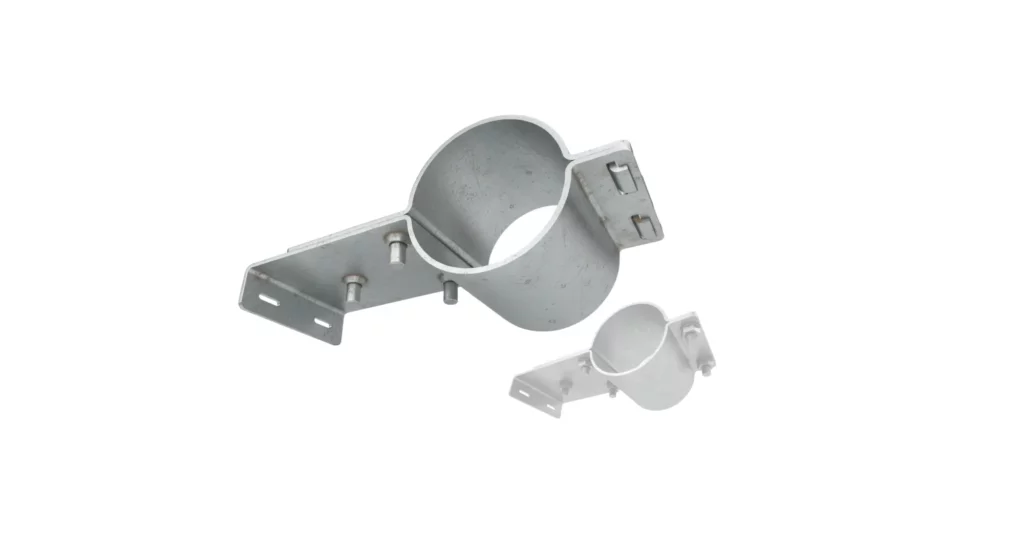
Sheet metal stamping die types and functions
Stamping dies define the geometry, tolerances, and surface quality of the finished part. Selecting the correct die type is one of the most important decisions in a stamping project.
What is a sheet metal stamping die
A stamping die is a precision tool that shapes sheet metal by transmitting the force applied by a press, through matched punch and die components. Dies are mounted in presses and designed for millions of cycles, rather than entailing built-in force generation.
Common die types
| Die type | Description | Typical use case |
|---|---|---|
| Single operation | Performs one operation per stroke | Low-volume, simple parts |
| Compound | Multiple cutting operations within a single stroke | Flat parts with holes |
| Combination | Performs cutting and forming operations together in one stroke | Moderate complexity parts |
| Progressive | Sequential operations in one die | High-volume production |
| Transfer | Part moved between stations | Large or complex parts |
Selecting the right die type
Selecting the correct stamping die format depends on part complexity, production volume, tolerance requirements, supplier capabilities, and budget.
- Simple flat parts or low-volume programs often use single-operation or compound dies, while high-volume, multi-feature components require progressive or transfer dies.
- Progressive dies are necessary when parts require multiple cuts and forms that must occur in a sequence (rather than a single progressive action. They allow high throughput and excellent repeatability.
- Transfer dies suit larger or deeper drawn parts where part handling between stations is required.
Early and precise alignment between part design and die strategy reduces tooling risk, controls cost, and ensures long-term production stability.
Sheet metal stamping design guidelines
Effective sheet metal stamping design reduces tooling cost, improves yield, and extends die life. While often neglected at the design phase of a part, processing and tooling considerations given early prominence can reduce tooling difficulties and part costs considerably, particularly for more complex parts.


Material selection for stamping
Material selection for stamped parts is critical to ensure manufacturability, part strength, and surface finish – and it has a significant effect on tool wear. Engineers must consider factors like ductility, yield strength, hardness, and corrosion resistance in order to balance the needs of the production process and the performance of the final part.
Softer and more ductile metals such as Aluminum and brass are easier to form and reduce tool wear, while high-strength steels or Titanium require careful die design and considerably higher press tonnage.
Material-thickness uniformity, springback characteristics, and compatibility with secondary processes such as coating/plating or heat treatment also heavily influence selection. Optimizing material choice minimizes production issues and ensures quality parts.
Bend radius and springback compensation
Minimum bend radii typically range from one to two times material thickness, varying with material properties and design needs. Some Springback must be compensated in die geometry.
Hole and feature placement
Effective hole and feature placement is key to quality in stamped metal parts, to maintain structural integrity, manufacturability, and assembly functionality.
- Holes should be positioned to avoid weak points or excessive deformation, keeping sufficient material around edges and bends.
- Features like cutouts, embosses, and flanges must account for material flow during forming to prevent tearing or wrinkling.
- Following generic spacing guidelines helps maintain tolerances and allow for accurate press alignment.
Designers should consider punch accessibility, die clearances, and progressive die sequencing for multi-step operations. Carefully considered placement also supports downstream assembly, fastener integration, and alignment with mating components, reducing manufacturing difficulties, need for jigging, and improving overall production efficiency.
Wall thickness and uniformity
Maintaining uniform wall thickness in stamped parts is crucial for consistent forming, structural integrity, and minimizing defects such as wrinkling or tearing. Unplanned variations in thickness can lead to uneven material flow, springback issues, and localized stress concentrations, compromising part quality. It is important to consider the thinning effects of drawing, as these can result in non-uniform wall thickness and anisotropic part properties that can create downstream challenges.
Designers should account for bend regions, feature density, and material distribution to achieve consistent thickness throughout the component. Careful selection of material gauges, die design, and stamping sequence helps deliver the required uniformity, easier assembly, and better repeatability across production runs.
Draft angles and form features
Draft angles in stamped parts allow smooth material ejection from dies, and reduce the risk of tearing or wrinkling. Even slight tapers – typically 1° to 3° – help metal flow during forming, improve tool life, and support consistent part quality.
Sufficient draft design is especially critical for deep draws and complex features in high-volume production. It can also be critical in reducing scuffing when forming parts from pre-plated material or material that must deliver cosmetic qualities without post-processing.
Designing for manufacturability
Design for manufacturability (DFM) in stamped parts focuses on optimizing part geometry, material choice, and feature placement to allow efficient, high-quality production with tolerance of tool wear.
Applying DFM principles helps minimize tooling wear, reduce scrap rates, and maintain required tolerances. Key considerations include;
- Selecting appropriate bend radii to avoid cracking
- Providing sufficient clearances for punches and dies to operate without impact/snag risk
- Maintaining uniform wall thickness to control material flow
- Hole and feature placement for structural integrity and assembly compatibility
- Sufficient draft angles for smooth ejection
- Account for springback compensation
DFM encourages collaboration with stamping engineers early in the design process, allowing for adjustments that reduce cost, tool complexity/weakness, and cycle time. Ultimately, DFM ensures that stamped parts can be produced reliably at scale while meeting functional and aesthetic requirements, reducing delays and downstream issues.
Sheet metal stamping tolerances whats achievable
Stamped parts can typically achieve dimensional tolerances of ±0.1mm to ±0.5mm, with critical features reaching ±0.05mm using precision dies and controlled press conditions. Angular tolerances generally range from ±0.5° to ±2°, while flatness and form tolerances depend on material, thickness, and die design, ensuring consistent quality across production runs.
Understanding tolerance classes
Tolerance systems for stamped parts commonly reference ISO 2768 for general dimensions and ASME Y14.5 for geometric tolerances. These standards guide designers in specifying permissible variations in size, form, and orientation, ensuring consistent quality and interchangeability across manufacturing processes.
Local tolerancing on critical dimensions is possible, but must be used with care as it typically imposes post-machining requirements that considerably increase costs.
Linear dimensional tolerances
Typical linear tolerances range from ±0.1 mm to ±0.5 mm.
Angular tolerances
Angular tolerances of ±0.5° are common, with tighter control possible in constrained features, although this can involve intricate tooling adjustments or increased tooling complexity.
Flatness and form tolerances
Flatness is influenced by residual stress and forming sequence, and can be hard to maintain with high precision. Where extreme flatness is required, it can become a driver of part design – or increase the need for post processing operations such as CNC ,machining or coining.
Factors affecting tolerance achievement
Material variation, die wear, and press alignment all contribute.
Tolerance specification best practices
Tolerances in stamped parts are used to define part fit, function, and assembly reliability. Tight tolerances improve precision but typically increase tooling complexity, press tonnage requirements, and production costs. Looser tolerances will ease cost and cycle time but risk misalignment or poor mating with other components.
Balancing tolerance requirements with manufacturability is a key skill in the design process and is typically improved by consultation with the manufacturer to understand the options and their influences.
Key stamping operations and techniques
Stamping can combine multiple operations to create finished geometry. These include punching, drawing, folding, embossing/coining, blanking etc.
Blanking and punching
Blanking cuts the outer profile while punching creates internal features. Blanking can be a first or last operation, depending on design and equipment considerations.
Bending and flanging
In these processes, the material is plastically deformed along defined bend lines. Complex considerations of material thinning, scuffing, springback and bend radius must be accommodated.
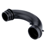
Drawing (or deep drawing)
Used to create cup-like or hollow shapes – this can be extreme, such as in forming a soda can – or much less significant, such as pressing in stiffening ribs.
Embossing and coining
This is used to add surface features such as markings/logos, or locally increase material density and tighten tolerances in necessary areas.
Post processing and surface finishing
Stamped parts typically require a range of secondary processing stages – for aesthetics, corrosion resistance, post-stamp machining for tight tolerances, fitting ancillary parts etc.
Deburring and edge refinement
Sharp edges are removed to improve safety and assembly. Sheared faces that result from punching and blanking can be imperfect – typically they are 30% thickness clean cut and 70% slightly rough and torn
Heat treatment
In many cases, steel parts require some degree of hardening or tempering to be applied – for example in forming sheet springs from stamped and folded high Carbon steel raw material.
Cleaning and polishing
This removes oils and debris from stamping operations. In some cases, such as with cosmetic stainless steel components, a polishing process is used to correct any machining marks and deliver a cosmetic quality surface.
Surface treatments and coatings
This includes plating, anodizing, painting, or passivation, depending on the nature of the material and the application.
Advantages and limitations of sheet metal stamping processes
| Process | Advantage | Limitation |
|---|---|---|
| Blanking | Fast removal of part outlines; high repeatability | Generates scrap material; limited to flat profiles |
| Piercing | Precise holes and cutouts in a single stroke | Tool wear increases with hard materials; limited hole size range |
| Bending/Forming | Creates 3D shapes and angles efficiently | Springback must be compensated; limited by material ductility |
| Deep Drawing | Produces complex, deep components | Risk of wrinkling or tearing; requires progressive dies |
| Embossing | Adds decorative or functional features | Depth and detail limited by die design; slower cycle time |
| Coining | High-precision detail; improved surface finish | High press tonnage required; slower production rates |
| Progressive Die Stamping | Multiple operations in one sequence; high-volume efficiency | Expensive tooling; inflexible for design changes |
| Transfer Die Stamping | Sequential operations on large parts; supports complex shapes | Large footprint; higher initial investment |
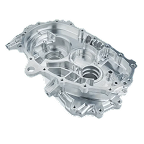
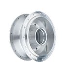
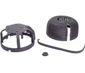
Applications across industries
| Industry Sector | Typical Applications | Recommended Materials | Preferred Die Types |
|---|---|---|---|
| Automotive / Transport | Body panels, chassis components, brackets, heat shields, reinforcement plates | Mild steel, high-strength steel, aluminum alloys | Progressive dies, transfer dies, combination dies |
| Aerospace / Defense | Aircraft fuselage panels, structural brackets, engine components, avionics housings | Aluminum alloys, titanium, stainless steel | Progressive dies, compound dies, combination dies |
| Electronics / Electrical | Enclosures, chassis, brackets, heat sinks, connector housings | Aluminum, brass, stainless steel | Progressive dies, combination dies, single-operation dies |
| Medical | Surgical instruments, device housings, implantable components, hospital equipment panels | Stainless steel 300 series, titanium, aluminum | Compound dies, combination dies, transfer dies |
| Consumer Products | Appliance panels, furniture components, decorative trims, electronic device casings | Aluminum, mild steel, brass, stainless steel | Progressive dies, single-operation dies, combination dies |
Custom sheet metal stamping tailored manufacturing solutions
Custom sheet metal stamping provides tailored and manufacturable solutions for parts with a huge spectrum of unique geometries, tight tolerances, or specialized material requirements. By designing dies and processes specifically for each component, manufacturers can produce precise, high-quality parts fast, and at lower cost than by any other process.
Custom stamping is ideal for low-to-high-volume production, though the cost-benefits increase with volume. It enables repeatable manufacture of complex shapes, and parts where applications where standard off-the-shelf solutions don’t exist.
This is where Jiga offers the strongest possible partnerships, acting as concierge/introducer to the best-fit of our extensive manufacturing networks.
Selecting a well-matched stamping partner reduces risk, improves production consistency, and supports successful delivery of both standard and highly specialized stamped components.
Summary
The sheet metal stamping process remains one of the most efficient methods for producing high-volume metal components when design tooling and tolerances are aligned. By understanding die types design rules and tolerance capabilities engineers can make informed decisions early. The Jiga platform connects you with qualified manufacturers capable of delivering precision stamped parts at scale.