
Surface finish is a simple subject that is often seen as hard to understand and communicate. There is a gap in many engineers’ knowledge – not a gap in understanding surface finish, but in the exact nature of the way it should be communicated.
Surface finish callouts are both underused and misinterpreted in engineering drawings, as a consequence of this. Engineers typically recognize the check mark symbol and the core finish values it depicts, but are often unable to fully interpret its various meanings, or specify it fully.
Mistakes in specifying surface finish can be expensive, adding unjustified cost by over-specifying, or missing performance/durability opportunities by under-specifying finishes that can have serious consequences.
A surface finish callout is not just a simple finish-controlling number; it encodes instructions as to how smooth a surface must be, how it should be produced, and how its texture is oriented. The common misinterpretation or over-specifying of it can trigger secondary operations, increase machining time, or result in part rejection.
This guide breaks down how to read, write, and interpret the requirements of surface finish callouts effectively. It covers symbol anatomy, roughness parameters/characteristics, lay direction and form, placement rules, the nature and dual causes of friction, and avoidance of the common mistakes in annotation.
Key takeaways
- A surface finish callout defines material removal methods, acceptable roughness, lay direction, and lay form.
- Ra is common but can be limited in informing about localized defects surface quality.
- Rz is more effective in describing surfaces for peak/valley-sensitive applications and characteristics such as occasional deep scratches, porosity, or pitting.
- Over-specification of finish can add unexpected cost, by imposing the need for secondary operations.
- The specified finish clearly needs to match the capability of the manufacturing process – or drive selection of a higher quality process.
What is a Surface finish callout?
A surface finish callout is an ISO standardized drawing symbol system used to define the required condition of a surface after manufacturing. It communicates how smooth, rough, or textured a surface must be, and it can also define how that condition should be achieved.
Two primary standards govern these symbols:
- ISO 1302 (international, metric-based)
- ASME Y14.36 (US, often inch-based)
While broadly aligned, they differ in formatting and units, which it is critical to understand, when working across global supply chains that adhere to one or other standard.
Surface finish vs surface roughness vs surface texture
- Surface finish is a general term describing overall surface condition. It is typically applied as a non-standardized description for cosmetic purposes, rather than a tight control of condition. This might involve specifying surfaces as flat, as-machined, fine-machined, grit-blasted, and others.
- Surface roughness defines micro-scale deviations measured by a variety of methods and standards. This includes Ra (average roughness in a limited stylus-travel evaluation), Rz (average peak to trough depth in similar measurement to Ra). A wide range of other assessment methods can review peak or trough dominance, RMS averaged roughness, peak sharpness, and more.
- Surface texture is a more complex assessment that includes elements representing roughness, waviness, and lay. This can be more important in bearing surfaces, guiding likely static and dynamic friction levels, wear expectations, galling risk etc.
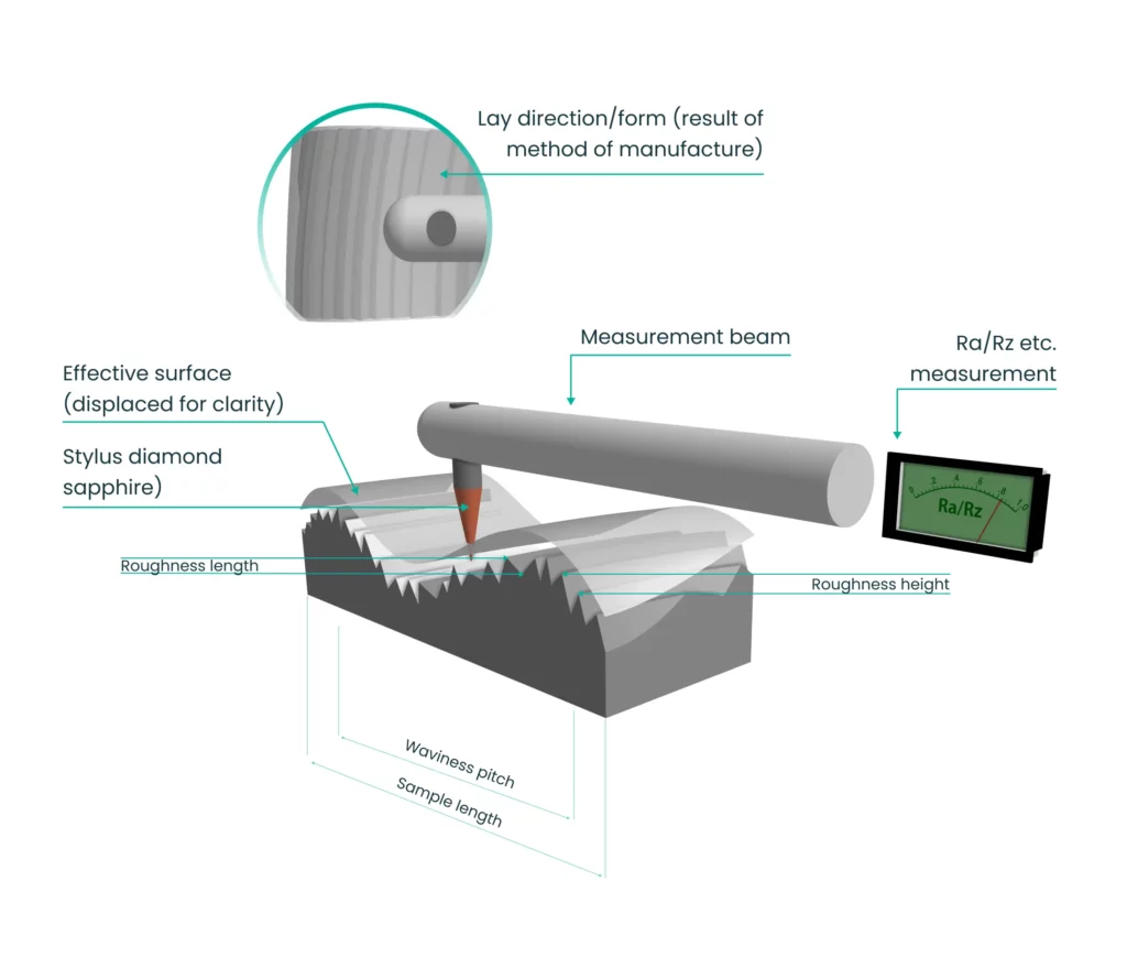
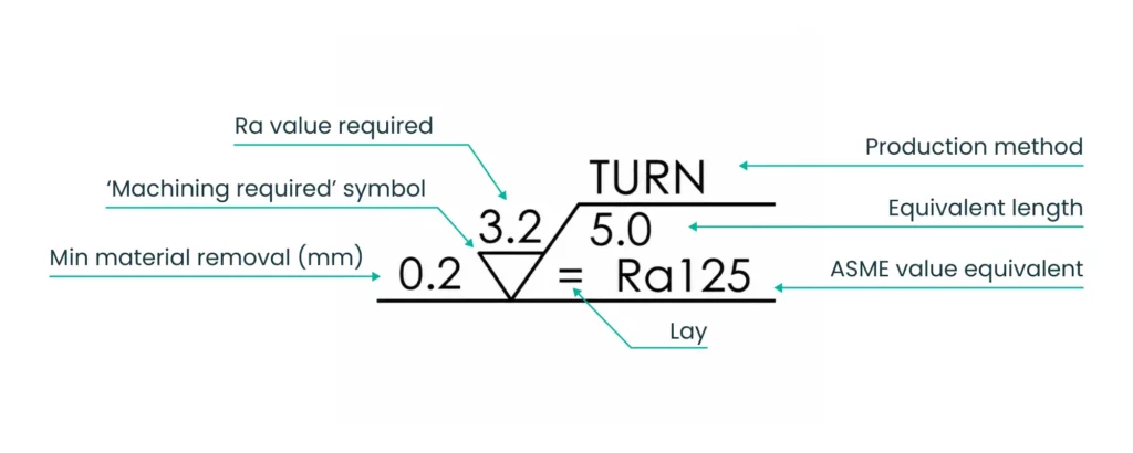
The anatomy of the surface finish symbol
The symbol is a check mark (V-shape) with defined annotation zones. The base symbol alone is meaningless, the annotations define the requirement.
The basic check mark symbol
Indicates a surface requirement exists. Without added values, it conveys no actionable information. These values/indicators include symbolic and numeric values that provide full guidance for manufacture
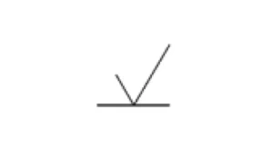
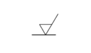
Variants: Material removal required, prohibited, or optional
- Bar added → Material removal required (machining needed)
- Circle added → Material removal prohibited (as-cast/formed)
Where each value sits on the symbol
| Position | Meaning |
|---|---|
| Above bar | Roughness value (Ra, Rz) |
| Left | Machining allowance |
| Below bar | Process (grind, hone, lap) |
| Upper right | Sampling length / waviness |
| Lower right | Lay direction |
Misplacing values changes the meaning of a callout in fundamental ways, creating cost/risk issues. This formatting is both rigorous and complete, when standard-compliantly executed. It must communicate the real and defined needs arising from the component design, function and interactions.
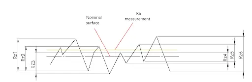
Ra, Rz, and other roughness parameters
Ra is widely used, but not always the most informative roughness measurement. It offers a more smoothed measurement that is informative overall, without informing about issues such as deep scratches, pitting or porosity.
Rz can offer greater insight about localized surface conditions within the scanned length, as a single significant divergence in peak or trough height/depth can have a greater impact on the measured result.
This makes Rz more useful in informing about surfaces that are liable to experience moving contact, wear risk, and static to dynamic friction moments.
Ra (average roughness)
| Ra (µm) | Ra (µin) | Characterization |
|---|---|---|
| 12.5 | 500 | Rough |
| 3.2 | 125 | Standard machined |
| 1.6 | 63 | Fine machined |
| 0.8 | 32 | Smooth |
| 0.4 | 16 | Very smooth |
| 0.1 | 4 | Precision |
Ra averages surface variation tends to hide peaks and valleys.
Rz (mean peak-to-valley)
Rz measures the average height difference between peaks and valleys.
It is most appropriate to use Rz when:
- Sealing surfaces matter
- Wear or contact behavior is critical.
- Peaks/valleys, rather than averages, drive the function of the tested surface.
When to use each
- Ra is most commonly applied in assessing/defining general engineering surfaces.
- Rz has greater utility in assessing functional interfaces such as seals, bearings, intermittent wear surfaces.
Reading lay direction symbols
Lay defines the direction and form of surface pattern created during manufacturing. It relates to the type of machining/processing the surface undergoes and can be used to pre-define machining techniques, in order to guide the process towards a more appropriate outcome.
| Symbol | Meaning | Machining process |
|---|---|---|
| = | Parallel | Turning |
| ⊥ | Perpendicular | Milling |
| X | Crossed | Grinding |
| M | Multidirectional | Honing |
| C | Circular | Facing |
| R | Radial | Disk grinding |
| P | Non-directional | Shot blasting |
Lay matters most in dynamic interfaces (bearings, seals), not static ones. Avoiding the additional frictional/stick-slip risk of the lay features of contacting parts coinciding can significantly reduce the risk of galling, micro-welding, and snatching during static friction onset.
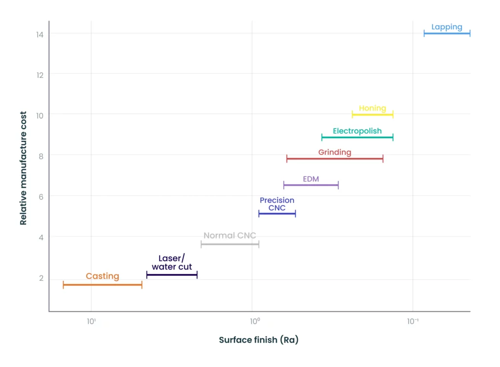
Common Ra values and the process that produces them
Every process has a default quality of finish, within a more easily achieved range. Specifying within this is effectively free or low cost, requiring only additional finishing passes to improve finish (within this range), avoiding process changes and additional setup.
| Process | Ra (µm) | Ra (µin) |
|---|---|---|
| Sand casting | 6.3–25 | 250–1000 |
| Injection molding | 0.8–3.2 | 32–125 |
| Rough milling | 3.2–12.5 | 125–500 |
| Standard milling | 1.6–3.2 | 63–125 |
| Fine machining | 0.8–1.6 | 32–63 |
| Grinding | 0.2–0.8 | 8–32 |
| Honing | 0.1–0.4 | 4–16 |
| Lapping | 0.05–0.2 | 2–8 |
| EDM | 0.4–3.2 | 16–125 |
Practical thresholds:
- Ra 3.2 µm (125 µin) is considered a standard CNC finish with sharp tools, appropriate coolant, and good quality machines in proper maintenance condition.
- Ra 1.6 µm (63 µin) requires controlled finishing steps in edged-tool machining. These are typically shallow finishing cuts with low material removal, reduced feed speeds, and even new cutters/inserts.
- Ra 0.8 µm (32 µin) or better requires grinding, lapping, honing or superfinishing, in the most extreme cases.
How to place a surface finish callout on an engineering drawing
Surface finish symbols can be applied in two distinct ways – though both are likely to be present on a given drawing, when the part has multiple functional surfaces that bring different requirements:
Per-surface callout
Higher-specification surfaces are likely to require local and face-limited definitions applied directly to a limited feature set, within a part.
This approach is used when surfaces differ from the component normal in surface-finish requirements, manufacture processes, or lay expectations.
Global callout
These specify general finish expectations that apply to all surfaces not individually annotated. They are typically defined in the title block of the drawing – and it is rare for a global callout to also require a high quality of surface finish. If it does, the logic of this should be checked before proceeding to manufacture.
Example: “UNLESS OTHERWISE SPECIFIED: Ra 3.2”
Best practice is to use global default at loosest acceptable finish, and locally override only where the requirement is clear.
Standards note
The two standards organizations use different measurement systems:
- ISO standards define/report Ra and Rz in micrometers (µm).
- The ASME handles data in imperial units, reporting finish for the same standards in microinches (µin).
Misreading units according to the wrong standard creates a 25 times error!
The hidden cost of over-specifying surface finish
Surface finish, when misspecified, becomes a major hidden cost driver, or a severe quality burden – depending on the direction of the error.
Typical impacts:
- Ra 3.2µm overspecified to 1.6µm can be expected to increase machining time by 15 to 25%, to allow for low depth, reduced feed-rate finishing cuts.
- Ra 1.6µm overspecified to 0.8µm may require grinding, causing a severe cost spike (2× or more) as this requires a whole setup, on other equipment.
- Specifying a finish of Ra 0.4 imposes lapping/superfinishing – specialist and highly skilled processes that add significant cost.
Before tightening a spec, ask:
- Is this surface functional or cosmetic?
- Is it static or moving?
- Does it interact with another surface?
Over-specification adds cost, typically without any performance benefit. The practical approach demands the lowest specified level that will deliver the required functionality, endurance, or appearance.
For cosmetic surfaces, it is often lower cost to add a plating stage, rather than directly improving the surface quality through in-process improvements.
DFM for surface finish: Designing with your process in mind
A mindful and consultative approach is beneficial in the early stages of a design, relying on standard guides to define the surface related functionality and deriving the necessary surface finish specification from this.
Experience pays dividends, so asking for support from manufacturers, and making comparisons with similar functional surfaces is the right choice.
Match the callout to process capability
Assume that most surfaces will be satisfactory with the finish that the process naturally produces, in normal (i.e. typical surface finish) operations.
Specify per surface, not globally
Only tighten the requirements where function demands it. Global callouts for uncontrolled, or basic standards of surface finish will suffice for most engineering surfaces. Not trying to control the lay of surfaces that are not in moving contact reduces the manufacturing restrictions that are otherwise imposed.
When to add secondary operations
Adding the requirement for grinding, honing, or lapping is a big cost-step, and this should only be taken when these specific finish levels are required for:
- Sealing faces, where mutual contact is the sole sealing mechanism OR a seal element such as an O-ring is used to achieve higher levels of seal.
- Bearing surfaces and wear resistance under intermittent abrasion contact.
- Precision motion in sliding surfaces that are not considered bearings – eg in adjustable positioning contact under load.
Communicating surface finish requirements to your supplier
Surface finish failures most often arise from communication or understanding/experience gaps. Adherent use of drawing standards call outs is important – but so is discussion with the supplier to make sure that a) the callouts reflect the real need and b) opportunities for cost saving have not been missed.
What a good quote conversation looks like
In detailed discussion with a supplier who is going to quote the required supply, a range of aspects should be addressed to avoid costly misalignments:
- Which surfaces exceed Ra 3.2 µm and why?
- Which require secondary operations, and are these correctly specified?
- Can your equipment achieve these values?
- Does toolpath direction and available equipment/methods match lay requirements as specified?
These discussions should clearly happen as part of the quotation process, before machining begins. Holding this discussion in review at inspection is a serious failure.
When to request inspection
It is by no means typical to request surface finish verification – it is necessary only for first-article inspection of mass production, or for the most critical surfaces in prototyping. Validating surface finish adds to the part price. Require it only where:
- Function depends on it – for seals and bearings.
- Expected finish is finer than Ra 1.6 µm.
- A new supplier or revised process is used, making it a first-article validation.
Common surface finish callout mistakes
Calling out a finish the process cannot achieve
Specifying a surface finish that lies beyond a process’s (or suppliers) capability creates a mismatch between design and manufacturing. Suppliers must add secondary operations or risk failing the requirement, increasing cost, lead time, and scrap.
It also leads to inconsistent quoting assumptions and tighter inspection burdens that can confuse the supplier selection.
The result is not just inefficiency but unclear manufacturing intent. Surface finish must align with functional needs and process capability, otherwise responsibility and risk shifts to the supplier driving up cost.
Tighter than function requires
Similarly, specifying tolerances or surface finishes that are tighter than functionally needed adds unnecessary cost and risk, without enhancing performance. It increases machining time, inspection effort, and scrap rates, and will force higher-precision processes, or costly secondary operations.
Suppliers often price in this risk, resulting in inflated quotes. Over-specification reduces process flexibility and risks reducing yield.
Engineering intent should focus on fit, function, and critical interfaces, applying tighter tolerances where they deliver real value.
No lay specified where it matters
Failing to properly specify surface lay where it matters creates ambiguity that can affect function and performance. Directional texture influences sealing, friction/stiction, wear, and fluid retention.
Without an appropriately defined lay, suppliers default to process-driven finishes, which can easily miss the design intent. This can result in leakage, premature wear, or cogging/spalling. Rework, testing delays, or field issues will result, with potentially large impacts.
Where surface interaction might be critical, lay should be explicitly controlled to match the function.
Conclusion
Surface finish callouts are one of the pivot-points where design intent meets manufacturing reality. Too many drawings quietly fail in this. A roughness value does not properly define a surface’s character and properties. It must reflect process capability, lay direction, functional requirements, and inspection methods. When misaligned, the result is predictably inflated costs, inconsistent quality, and parts that underperform or waste money.
The most effective drawings are intentional. They apply tight finishes where product or component-function demands it, align requirements with achievable process windows. They also communicate clearly: specifying Ra or Rz where appropriate, specifying lay when direction is influential, and avoiding ambiguity.
At an advanced level, surface finish is less about numbers and more about control of surface interactions – how they move, seal, or wear over time. Thinking beyond the drawing makes a better product – consider how the part will be machined, how it will be evaluated, and how variation might influence performance in the real world.
Surface finish callouts reduce cost, improve yield, and increase confidence across the supply chain – when they are done right.