
Process capability analysis has historically been treated as a that is applied after tooling is complete.
That’s backwards.
By the time a supplier is measuring Cpk on production parts, the decisions that determine capability have already been set in almost-stone. The drawing defines the tolerances. The mold designer selects the gate locations. Cooling circuits are machined into hardened steel. The processing window has been largely established.
If the process cannot achieve the required capability, changing machine settings is rarely sufficient. The root cause eventuated in early-mid design and got locked in.
Experienced manufacturing engineers therefore view injection molding process capability as the outcome of an engineering workflow, rather than a straightforward quality metric:
GD&T → Moldflow simulation → Cooling design → DOE → Capability study → PPAP → Production approval
Break any link in that chain and outcome-Cpk is at risk.
Treat capability as a design objective from the outset, and production can be significantly more predictable. Existing guidance typically explains Cp/Cpk, Moldflow simulation or PPAP individually. In practice, they are a matrix engineering activities, not a waterfall. They should be processed in parallel.

Why injection molding process capability starts at the drawing, not the press
Many capability issues begin with an engineering drawing that asks for precision that provides no functional benefit.
Specifying ±0.05 mm is easy.
Producing that tolerance repeatedly across hundreds of thousands of molded parts is considerably more difficult and expensive.
Every tight tolerance applied to a drawing drives challenges in:
- tooling complexity
- mold steel selection
- cooling circuit design
- process qualification
- inspection effort
- manufacturing cost
That is why good GD&T is fundamentally an exercise in cost engineering as much as dimensional control.
If you’re defining molded parts for production, it’s worth reviewing Jiga’s guides to Injection Molding Design, GD&T Fundamentals, and Design for Manufacturing (DFM) before finalising production drawings. Those topics provide the foundation for achievable capability targets.
Identify critical-to-quality features first
Not every dimension deserves the same capability requirement.
The most effective drawings distinguish between dimensions that affect product function, and those that describe low-constraint geometry.
| Feature Type | Capability Priority |
|---|---|
| Sealing surfaces | Critical |
| Bearing fits | Critical |
| Snap-fit interfaces | Critical |
| Cosmetic surfaces | Functional |
| External envelope | Functional |
| Non-functional geometry | Reference |
Assigning the tightest tolerances only to critical-to-quality (CTQ) features allows capability studies to focus on dimensions that genuinely determine product performance, instead of consuming inspection time on features that carry little engineering significance.
ASME Y14.5 provides the language for GD&T. Engineering judgement determines where those controls are justified.
GD&T drives capability long before production
GD&T is frequently viewed as an inspection language. It is also the semiotics of manufacturing.
A positional tolerance applied to four mounting bosses immediately affects:
- gate location
- cavity pressure balance
- shrinkage compensation
- cooling layout
- fixture design
- inspection strategy
Every reduction in tolerance narrows the acceptable process window.
Thus, over-specifying non-critical dimensions increases tooling cost, process development time, cycle time, inspection effort, and scrap – without proportionally enhancing product performance.
A useful design review therefore begins with a simple question:
Which dimensions genuinely justify a capability study?
That conversation often sensitizes the design process to cost, before tooling has even been quoted.
Capability cannot exceed the design
A highly capable molding machine cannot consistently manufacture dimensions that the tool itself cannot support.
Likewise, an excellent mold cannot compensate for unrealistic GD&T.
- Capability is cumulative.
- Drawing details influence tooling.
- Tooling influences processing.
- Processing determines dimensional variation.
- Inspection merely confirms the result.
This perspective also adjusts how suppliers must be evaluated. Rather than asking whether a supplier can “hold ±0.05 mm,” ask what engineering evidence supports their capability claims.
A credible answer should reference tooling design, moldflow simulation, cooling strategy and historical capability data, and provide exemplar moldings, not simply pronounce on machine accuracy.
Planning a tight-tolerance injection molding program?
Before tooling begins, Jiga works with engineering teams to review GD&T, manufacturing strategy and supplier capability together, helping identify capability risks while changes are still inexpensive. If your drawing is about to become steel, this is the point where an independent engineering review usually delivers the greatest value.
Using moldflow simulation to predict capability before cutting steel
Once the drawing establishes the capability target, the next evaluation is whether the proposed tooling can realistically achieve it.
Moldflow simulation is where engineering begins answering that question, long before steel is machined – ideally as tooling in planning.
Many engineers dramatically underestimate the value in moldflow analysis.
An effectively executed moldflow study predicts whether the proposed mold is physically capable of delivering the dimensional stability required by the drawing. It allows engineers to identify capability risks while geometry, gate locations and cooling circuits remain inexpensive to change.
Viewed correctly, Moldflow is not a design tool.
It is a process capability prediction tool.
If you’re unfamiliar with how simulation integrates into production development, Jiga’s articles on Moldflow Simulation, Injection Molding DFM, and Prototype to Production Injection Molding provide useful background before committing to production tooling.
What moldflow actually predicts
An engineering-grade moldflow report should explain how the polymer behaves inside the cavity, not simply whether the cavity fills successfully.
Among the most valuable outputs are:
- Fill pattern and fill time
- Pressure distribution
- Weld-line locations
- Air traps
- Volumetric shrinkage
- Fibre orientation
- Sink prediction
- Warpage by X, Y and Z axes
- Cooling efficiency
- Clamp force requirement
Together these results provide a prediction of dimensional stability before a single component has been molded.
This shifts engineering discussions from opinion to evidence.
Instead of asking whether a design “should be okay,” you can ask whether the predicted warpage exceeds the tolerance band allocated to a critical feature.


Warpage is usually the real capability problem
When production capability deteriorates, machine settings often receive the blame.
In reality, dimensional instability is far more likely to originate from part deformation than from inconsistent machine performance.
Warpage occurs because polymers rarely cool uniformly.
Differences in wall thickness, cooling efficiency, fibre orientation and volumetric shrinkage create internal stresses that continue moving the part after it leaves the cavity.
A process can therefore appear perfectly stable while still producing components that consistently fail dimensional inspection.
Typical causes include:
- non-uniform cooling
- differential shrinkage
- asymmetric wall thickness
- poor gate location
- uneven packing pressure
- fibre-induced anisotropy
This distinction is important.
A capable molding machine cannot compensate for a component that has been designed to warp.
If Moldflow predicts deflection larger than the available tolerance window, redesigning the geometry or tooling is almost always more effective than attempting to “tune out” the problem on the press.

Gate location (and type) is a capability lever
Gate location influences much more than filling.
It affects:
- weld-line position
- fibre orientation
- packing efficiency
- residual stress
- shrinkage direction
- cosmetic appearance
- dimensional repeatability
Moving a gate by only a few millimetres can relocate weld lines away from structural features, improve packing pressure in critical regions and significantly reduce differential shrinkage.
For engineers, gate design should therefore be considered alongside GD&T rather than after tooling begins.
The drawing establishes the capability requirement.
Gate location helps determine whether that requirement is physically achievable.
What you should ask to see
Simply being told that a Moldflow analysis has been completed provides very little assurance.
Instead, request the engineering outputs that support capability decisions.
A useful report should include:
| Moldflow Output | Why It Matters |
|---|---|
| Fill-time animation | Confirms balanced cavity filling and identifies hesitation areas |
| Weld-line map | Highlights potential structural and cosmetic weaknesses |
| Volumetric shrinkage map | Predicts dimensional variation before tooling |
| Warpage analysis | Compares predicted deformation against tolerance requirements |
| Fibre orientation | Critical for reinforced engineering polymers |
| Cooling analysis | Demonstrates whether temperature distribution is uniform |
| Pressure profile | Indicates whether the selected gate strategy is practical |
When suppliers willingly discuss these results, engineering conversations become significantly more productive than simply reviewing a quotation.
Jiga helps engineering teams review Moldflow results alongside tooling strategy, production materials and supplier capability, ensuring simulation outputs translate into practical manufacturing decisions rather than remaining isolated reports.
Discuss your tooling strategy with a Jiga manufacturing engineer before steel is cut.
Cooling design is where injection molding Cpk lives or dies
Ask experienced mold designers what determines production capability, and many will answer with one word:
Cooling.
Cooling receives far less attention than gate design or machine settings, yet it governs almost every aspect of dimensional repeatability.
It determines:
- cycle time
- residual stress
- crystallinity
- shrinkage
- warpage
- dimensional stability
- long-term process consistency
The Injection Molding Handbook by Rosato, widely referenced in Autodesk Moldflow documentation, estimates that cooling typically accounts for 50% or more of the total molding cycle. That means improvements to cooling influence both production economics and process capability simultaneously.
Uniform cooling creates uniform parts
The objective is not simply to cool the polymer. It is to cool every region at nearly the same rate. If one side of a housing cools faster than the other, the component shrinks unevenly.
Uneven shrinkage produces residual stress. Residual stress produces warpage. Warpage reduces Cpk.
The chain is remarkably direct.
Good cooling design therefore focuses on temperature uniformity rather than simply reducing cycle time.

Conventional vs. conformal cooling
Traditional cooling channels are drilled in straight lines. For simple geometries, this approach works well. Complex parts present a different challenge.
Deep ribs, bosses and varying wall sections often place critical regions too far from conventional cooling channels, creating hot spots that extend cooling time and increase dimensional variation.
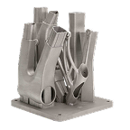
Conformal cooling, typically produced using metal additive manufacturing, allows cooling channels to follow the contour of the cavity.
This can improve temperature uniformity dramatically and published case studies have reported warpage reductions of approximately 15 – 40% compared with conventional channel layouts, depending on part geometry and material.
Conformal cooling should not be selected simply because it is advanced.
It should be selected when the required capability cannot be achieved economically using conventional tooling.

From DOE to PPAP: Validating injection molding process capability in production
Once the mold has been designed, simulation completed and cooling validated, the next objective is proving that the manufacturing process can repeatedly produce conforming parts.
This is where many organisations make another common mistake. They treat capability studies as paperwork. In reality, capability studies validate the entire manufacturing system.
- Machine.
- Mold.
- Material.
- Operator.
- Measurement system.
- Inspection method.
If any one of these changes significantly, capability should be questioned again.
Establish the process window with DOE
Before calculating Cpk, engineers first need to understand how robust the process actually is.
This is the purpose of Design of Experiments (DOE). Rather than adjusting one machine parameter at a time, DOE deliberately varies several inputs simultaneously to understand how they interact.
Typical variables include:
- Melt temperature
- Mold temperature
- Injection speed
- Pack pressure
- Hold pressure
- Hold time
- Cooling time
- Screw recovery
- Cushion
The objective is not simply to find one “good” process.
It is to establish a stable operating window, where normal production variation still delivers acceptable parts.
A process capable only at one precise machine setting is not a capable production process.
Cp, Cpk, Pp and Ppk answer different questions
Although often used interchangeably, these indices measure different aspects of production performance.
| Metric | Purpose | Typical Application |
|---|---|---|
| Cp | Theoretical process capability assuming the process is centred | Early process optimisation |
| Cpk | Actual capability including process centring | Production approval |
| Pp | Overall long-term process performance | Initial production assessment |
| Ppk | Actual long-term performance including drift | Short-run validation and monitoring |
For most production programs:
- Ppk is useful during initial sample runs when limited production data exists.
- Cpk becomes the primary approval metric once the process has stabilised.
This distinction matters because early sample data often reflects process development rather than mature production.
Capability targets depend on industry risk
Not every product requires the same capability.
Typical expectations are:
| Industry | Typical Minimum Cpk |
|---|---|
| General industrial products | 1.33 |
| Automotive special characteristics (IATF 16949) | 1.67 |
| Medical, aerospace and safety-critical programs | 2.0 or higher |
According to AIAG SPC guidance, a Cpk of approximately 1.33 corresponds to roughly 63 defective parts per million, while 1.67 reduces the theoretical defect rate to around 0.6 parts per million under normal distribution assumptions. These targets reflect different levels of acceptable manufacturing risk rather than arbitrary quality goals.
Reliable capability requires reliable measurement
Capability calculations are only as trustworthy as the measurement system.
If inspection equipment introduces excessive variation, calculated Cpk values become meaningless.
A Measurement System Analysis (MSA), including Gage R&R (repeatability and reproducibility), should therefore precede formal capability studies.
As a general guideline, the measurement system should consume less than 10% of the specified tolerance for SPC data to be considered reliable under AIAG MSA guidance.
PPAP validates the entire manufacturing system
Production Part Approval Process (PPAP) is often misunderstood as a documentation exercise.
It is better viewed as evidence that every element required for stable production has been validated.
Depending on the required PPAP level, documentation may include:
- Dimensional inspection results
- Material certifications
- Approved Moldflow reports
- Process flow diagram
- Control plan
- PFMEA
- MSA and Gage R&R
- Capability study
- Tooling records
- Appearance approval (where applicable)
Together these documents demonstrate that production is repeatable rather than merely successful once.
If you’re preparing for production release, Jiga’s articles on PPAP, First Article Inspection (FAI) and Production Part Validation provide additional guidance on documentation and supplier expectations.
Cost engineering: Capability has a price
Higher capability is achievable. It is rarely free. Every increase in dimensional capability influences:
- tooling complexity
- steel grade
- cooling sophistication
- qualification time
- inspection effort
- maintenance strategy
This relationship is why experienced engineers avoid over-specifying tolerances.
The objective is not to achieve the highest possible Cpk. It is to achieve the necessary Cpk.
Where cost begins to escalate
Moving from a process capable of Cpk 1.33 to 1.67 often requires more than tighter machine control.
It may require:
- improved cooling symmetry
- hardened tooling
- independent cavity cooling
- additional process validation
- tighter resin control
- more extensive DOE
- increased inspection frequency
For genuinely critical characteristics, these investments are justified.
For cosmetic or non-functional dimensions, they frequently are not.
One of the most valuable engineering discussions therefore asks:
“Does this feature genuinely require this capability?”
That single question often removes unnecessary cost, before tooling is ordered.
Total cost of quality
Rejecting 3% of production because capability is inadequate is potentially very expensive. So is overengineering every feature to achieve aerospace-level capability.
The optimum solution usually lies between these extremes.
The most successful engineering teams negotiate capability requirements around product function, risk and lifecycle cost rather than applying identical targets to every dimension.
Jiga works alongside engineering teams to review capability requirements, supplier validation packages, PPAP documentation and production readiness before volume manufacture begins. The objective isn’t simply to approve a tool. It’s to ensure the entire manufacturing system is capable of delivering parts on time and on specification.
Production capability checklist
Before approving production, confirm:
- CTQ dimensions identified
- GD&T reviewed against manufacturing capability
- Moldflow completed and reviewed
- Cooling analysis validated
- DOE establishes a stable process window
- Gage R&R completed
- Cpk target agreed
- PPAP documentation complete
- Control plan approved
- Supplier capability demonstrated with statistically valid data
Key takeaways
The most important lesson about injection molding process capability is that it does not begin at the molding machine.
It begins with engineering decisions made long before production starts.
A well-defined drawing establishes realistic capability targets. Moldflow simulation tests whether those targets are achievable. Cooling design determines whether they remain stable throughout production. DOE defines a robust processing window, while PPAP confirms that the complete manufacturing system can consistently deliver conforming parts.
Viewed this way, Cp and Cpk are not isolated quality metrics. They are the measurable outcomes of good engineering.
Teams that connect GD&T, simulation, cooling, tooling and validation into a single workflow avoid many of the problems that traditionally emerge during first article inspection and production launch. Rather than reacting to capability failures after steel has been cut, they design capable processes from the beginning.
That is ultimately the difference between producing molded parts and building a manufacturing process capable of producing them repeatedly, predictably and at scale.
Frequently Asked Questions
What is a good injection molding Cpk?
For most industrial applications, 1.33 is considered an acceptable production target. Automotive special characteristics commonly require 1.67, while many medical and aerospace programs target 2.0 or higher depending on risk and customer requirements.
Can Moldflow predict Cpk?
Not directly.
Moldflow simulation predicts the physical behaviour that influences process capability, including warpage, shrinkage, fibre orientation and cooling balance. It helps engineers determine whether the required Cpk is realistically achievable before tooling is manufactured.
Why does cooling have such a large effect on capability?
Cooling governs residual stress, shrinkage and dimensional stability. Since it also accounts for over 50% of the molding cycle, poor cooling design affects both manufacturing cost and process capability simultaneously.
Should every dimension have a capability study?
No.
Capability studies should focus on critical-to-quality characteristics that influence product function, sealing, safety or assembly. Applying identical capability requirements to every dimension unnecessarily increases manufacturing cost.
What should I request from an injection molding supplier?
Ask for more than a quotation.
Request evidence supporting process capability, including Moldflow outputs, cooling analysis, DOE results, capability studies, Gage R&R data and the relevant PPAP documentation. These provide a much clearer indication of production readiness than price alone.