
Sheet metal prototyping fabrication transforms a CAD model into a functional metal component, with little intervening between idea and realisation, as long as design rules are followed and tool selection is feasible.
Unlike prototypes produced through additive manufacturing, sheet metal prototypes are manufactured through essentially the same fabrication processes that will be used during production. Variations result through the transition from one to many, but the formational actions remain virtually identical:
- laser cutting,
- press brake forming,
- welding,
- hardware insertion,
- finishing
As a result, this class of prototype provides realistic – and often complete – validation of fit, form, assembly, strength, and manufacturability before significant investments are made in tooling.
When the design follows established DFM principles and utilizes stocked materials, turnaround times of a few business days are routinely achievable. However, non-compliantly designed parts tend to create delays, rework, and inflated costs that can exceed the realistic part-budget.
This guide illustrates the processes, materials, design considerations, and sourcing strategies that enable engineers to obtain successful sheet metal prototype outcomes, in the first iteration. It illustrates how the Jiga relationship can enhance your supplier engagement, without obstructing communications.
Key takeaways
- Sheet metal prototypes use production-representative fabrication processes and production-real materials, making them ideal for product functionality validation.
- Simpler parts/assemblies manufactured from stock materials can often be delivered within days, where capacity allows.
- Most prototype delays originate from avoidable DFM issues, often quite evident in basic evaluation of the CAD model.
- Prototype fabrication typically avoids early investment in expensive hard tooling requirements.
- Early and direct communication with fabricators significantly reduces failure/rework risk.
What is Sheet Metal Prototype Fabrication?
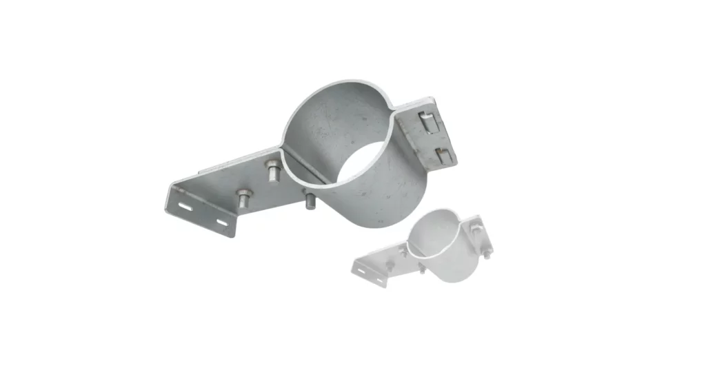
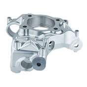
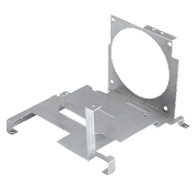
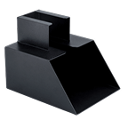
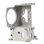
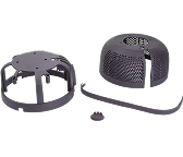
Sheet metal prototype fabrication is the manufacture of low-volume, real-material components that can be directly used to performance-validate a design before full production, without the normal prototype interpretation issues. Common examples include:
- Electronic enclosures
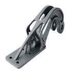
- Mounting brackets
- Chassis components
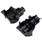
- Covers and panels
- Machine guards
- Structural and functional assemblies
The process typically begins with CNC laser cutting to produce flat blanks. These blanks are then formed using press brakes and simple tools. Assemblies may require to be welded or assembled using mechanical fasteners. Prototypable real-production finishing operations may include powder coating, anodizing, passivation, plating, or bead blasting.
Unlike mass-production stamping, prototype fabrication requires no dedicated and costly hard tooling. This allows engineers to modify geometry, performing design iterations and prototype cycles rapidly and economically.
Jiga engages as concierge, introducing suppliers from a vetted stable and standing at your right hand to support your direct and effective communications through RFQ, DFM and production. We do not stand between, nor take actions for you.
When should you use sheet metal prototyping?
Sheet metal prototyping is most appropriate when:
Functional testing is required
Material properties closely match production parts, allowing realistic evaluation of:
- Strength
- Fatigue resistance
- Thermal performance
- Assembly sequences/processes
Design iteration is expected
Prototype fabrication supports rapid design changes, side-stepping complex and expensive tooling modifications, as tooling can be delayed until design signoff.
In simple cases, a first part may be identical to the thousandth part – but in the real world, early designs evolve and are refined through the early stages of prototyping and transfer to production.
Production volumes are uncertain
Before committing to expensive, sequential stamping die sets, prototype fabrication allows validation of market demand and engineering assumptions.
Many parts undergo a soft transition from prototype (1-10 parts), to low volume manual production (10-100~ parts), to increasingly tooled and high volume. Unlike in many production areas, the product of each stage can be functionally and cosmetically indistinguishable.
Assembly validation matters
Fit-up, hardware installation, access clearances, and serviceability can all be verified before production release.
Core fabrication techniques
While the equipment performing an operation may differ greatly in cost and production capacity between prototype and production, the actual functional execution of each operation can be indistinguishable in the finished part.
Cutting
Laser cutting is the dominant process for sheet metal prototypes.
Benefits include:
- Fast turnaround
- High dimensional accuracy
- Excellent edge quality
- Capability for intricate geometries
Fiber lasers commonly process:
- Aluminium
- Stainless steel
- Mild steel
- Copper alloys
For thicker materials plasma cutting may be more appropriate. For heat-sensitive materials, waterjet cutting may be preferred.
Many organizations classify ECOs by severity.
Forming
Press brake forming converts flat blanks into three-dimensional components.
Important design considerations include:
- Bend radii and reliefs
- Material springback
- Flange lengths
- Tool accessibility
CNC press brakes routinely achieve angular accuracy of ±0.5° or better. Skilled manual operations on one-off parts can typically deliver equal quality.
Standard embossing tools are usually available, so engaging with the supplier early is wise, to ensure that intended bosses are feasible.
Assembly
Assembly may involve:
- TIG welding
- MIG welding
- Spot welding
- Riveting
- Self-clinching hardware
For prototypes, mechanical fastening often enables easier modification between iterations. It’s notable that the volume advantages resulting from tooling and automated assembly/welding come at a high price, so manual assembly dominates at mid and even high volumes.
Hardware insertion
Many production sheet metal assemblies rely on installed hardware such as:
- PEM nuts
- PEM studs
- Standoffs
- Rivet nuts
- Captive fasteners
- Catches, hinges, handles, locks, bumpers etc.
Designing these features into prototypes enables realistic assembly validation and often eliminates secondary machining operations.
Key common materials for sheet metal prototypes
Aluminium (5052 and 6061)
Advantages:
- Lightweight
- Corrosion resistant
- Easy to form
- Widely available
Common applications:
- Enclosures
- Aerospace brackets
- Consumer products
Stainless Steel (304 and 316)
Advantages:
- Excellent corrosion resistance
- High strength
- Attractive finish
Applications:
- Food equipment
- Medical devices
- Marine systems
Carbon steel (CRS and HRS)
Advantages:
- Low cost
- High availability
- Good weldability
Applications:
- Industrial machinery
- Structural brackets
- Equipment frames
Copper and brass
Advantages:
- Electrical conductivity
- Decorative appearance
- Corrosion resistance
Applications:
- Busbars
- EMI shielding
- Decorative components
How to choose the right sheet metal
Multiple factors influence material selection:
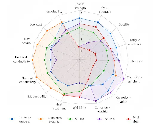
Mechanical performance
Consideration of the various dimensions of strength required will have a significant impact on material selection:
- Yield strength
- Fatigue resistance
- Impact resistance
Corrosion performance
The spread of corrosion challenges parts may face is very wide – from anodyne to highly corrosive:
- Dry indoor environments
- Ambient outdoor hot, cold, or cycling
- Marine and swimming pool (chloride ion exposure)
- Industrial/food/corrosive/acidic exposures
- Human body exposure – long or short term
- Radiation and vacuum – high altitude/orbital
Each of these imposes requirements in the base material, and any protections that may be required such as paint, plating, passivation etc.
Manufacturability
All sheet metal parts will require ‘extraction’ from a blank sheet. The ideal method is affected by thickness, material, post processing needs, quality issues and available technologies.
While most materials CAN be cut by most of the available methods, there are exceptions such as highly reflective metals or red metals (Copper, brass, bronze) which react poorly to Carbon dioxide laser cutting.
In terms of forming the cut part, malleability (the ability to be deformed plastically by applied compressive load/hammering) and ductility (the ability to be deformed plastically by tension) can influence material choice for a part. Titanium and some superalloys are harder to bend and can suffer higher cracking risk.
Weldability can be a selection influence. This varies widely between materials, ranging from essentially not weldable (some Aluminum alloys, Beryllium-Copper); through at-risk due to corrosion sensitization, precipitate weakness, and oxide entrapment (various stainless steels), or Hydrogen entrapment/oxide embrittlement (Titanium and its alloys); through to highly weldable (steels, many Aluminum grades).
Lead time
Stock gauges of standard materials often reduce delivery times dramatically.
The effect of workability can also heavily influence production – Titanium and superaloys deliver manufacturing challenges that limit productivity and severely increase costs,
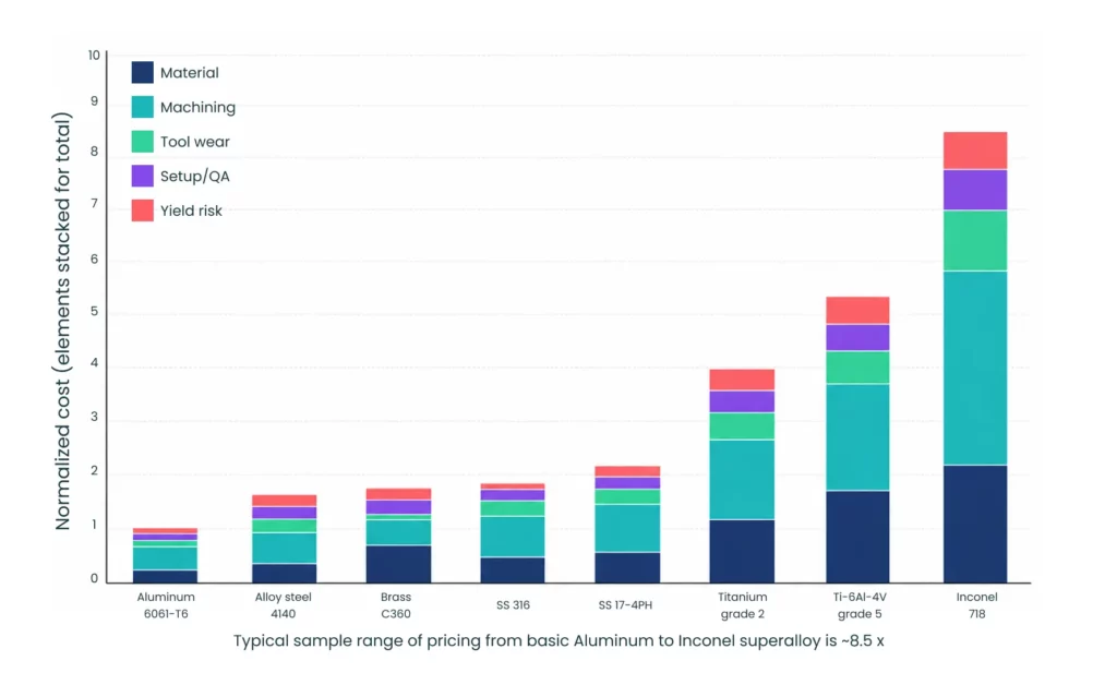
Cost
Material costs vary substantially. Carbon steel generally offers the lowest material cost, while copper and stainless alloys carry premiums.
The optimal choice often balances the various considerations, rather than maximizing a single factor. In some cases – such as parts under high corrosion environments, or suffering high cyclic loading, or requiring narrow certifications in specialist sectors, the selection process is simplified by one overwhelming need.
Designing for manufacturability (DFM)
Perhaps the most significant influence on cost and manufacturability for a part is the compliance with basic design principles. Creating avoidable, and challenging design elements that present barriers to easy production, high quality, and minimized cost happen too often.
Maintain consistent thickness
Uniform thickness is imperative for simple and practical, one-piece forming. The manufacture steps involved in thinning sections of a uniform sheet material, by stretching, machining, or plastic pressing are costly, difficult and create dimensional inconsistency.
Use appropriate bend radii
As a starting point, internal bend radius must be strictly equal to or greater than the material thickness. Thus the minimum outer radius of a bend is twice the material thickness
Tighter bends, or harder/more brittle materials increase cracking risk and impose larger minimum bend radii.
Keep holes away from bend lines
Recommended minimum hole-to-bend distance is twice the material thickness
This reduces the risk of distortion during forming, where the hole edge is stretched and drawn into the pre-bend area as material flows locally.
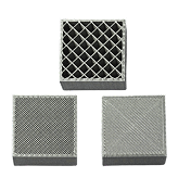
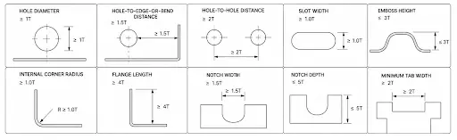
Avoid excessively narrow features
Small tabs and narrow sections are vulnerable to deformation. The guidelines around feature size and its relationship with surrounding material can be expressed in this sequence of diagrams:
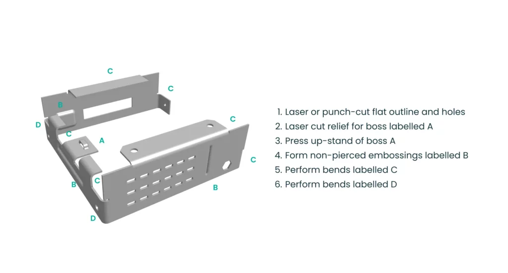
Design for tool access
Ensure bends and features remain accessible to standard press brake and press tooling.
In many cases, maintaining access is a function of sequencing of actions, rather than the final expected profile. Where there is any doubt, it is sensible to discuss design options with the potential manufacturer, as early DFM input consistently simplifies manufacture and avoids cost bloat.
A key consideration in forming a sheet metal part is maintaining tool access, generally enabled by sequencing operations in an order that doesn’t prevent access for ‘later’ stages
Minimize weld count, optimize access
Reducing weld-count generally improves:
- Cost
- Lead time
- Distortion control
Reducing weld intensity by not seam welding, by resistance spot welding and by avoiding welded joints where loading permits will all reduce cleanup, heat damage and cost.
Simplify assemblies
Consolidating multiple components into fewer fabricated parts often reduces total manufacturing cost. It is often possible, by accepting some component complexity, to reduce part count in this way. The relative costs and benefits can be large, where labor costs are high or where interconnects may be considered as failure risk points – for example in heavily loaded or variably loaded aircraft skin parts.
Surface finishing and post-processing
Common finishing options include:
| Finish | Benefits |
|---|---|
| Powder coating | Durable, attractive appearance |
| Anodizing | Corrosion protection for aluminum |
| Passivation | Improves stainless corrosion resistance |
| Zinc plating | Corrosion protection for steel |
| Bead blasting | Uniform cosmetic appearance |
| Brushing | Architectural finish |
Surface finishing requirements should be discussed early because they profoundly influence weld preparation and dimensional tolerances. They can also drive material selection – for example in the choice of pre-plated sheet steel for mild corrosion-risk panels, removing the post processing requirement entirely.
Prototype tolerances and inspection
Typical prototype tolerances include:
- Laser cutting: ±0.1–0.2 mm
- Press brake dimensions: ±0.25–0.5 mm
- Angular tolerances: ±0.5–1.0°
Inspection methods may include:
- Vernier calipers
- Height gauges
- CMM inspection
- Laser scanning
Critical dimensions should be clearly identified on drawings.
can also drive material selection – for example in the choice of pre-plated sheet steel for mild corrosion-risk panels, removing the post processing requirement entirely.
Sheet metal prototype vs production tooling
Prototype fabrication offers:
- No hard tooling
- Fast iteration
- MOQ of one
- Design flexibility
Production tooling offers:
- Lower unit costs
- Higher throughput
- Greater consistency at scale
Typical mass-production tooling investments range from a few thousand dollars to several hundred thousand, depending on complexity and automation implications that apply at large volumes.
For many brackets and enclosures, prototype fabrication remains economical up to approximately a few hundred units, giving sufficient time for complete design evaluation/stabilization before commitment to tooling.
Sheet metal vs CNC machining for prototyping
| Factor | Sheet Metal | CNC Machining |
|---|---|---|
| Material Efficiency | High | Lower |
| Speed | Fast | Moderate |
| Large Panels | Excellent | Poor |
| Complex 3D Geometry | Limited | Excellent |
| Weight Reduction | Excellent | Moderate |
| Cost for Thin Parts | Low | Higher |
Sheet metal is typically preferred for enclosures, panels, and brackets, while CNC machining excels for thicker and more complex components.
Working with your fabrication partner
Successful prototyping is fundamentally a communication exercise.
Before submitting a design:
- Confirm material availability
- Review bend requirements and other core DFM aspects
- Discuss weld expectations – and how to minimize them
- Identify critical dimensions
- Verify finishing standards and surface treatment requirements
The best fabrication partners perform detailed DFM to identify manufacturability issues before production of the first part, reducing both cost and schedule risk.
Frequently Asked Questions
What file formats are required for quoting?
STEP files are preferred. DXF drawings and PDF engineering drawings are also commonly requested.
What is the minimum order quantity?
Most prototype fabricators generally accept quantities as low as one part, particularly for more challenging components or the simplest parts.
How accurate are sheet metal prototypes?
When properly designed, prototype parts closely mirror production components in geometry, material properties, and assembly performance.
How quickly can sheet metal prototypes be produced?
Simple designs using stocked materials are commonly delivered within 2–5 business days.
Can production hardware be installed in prototypes?
Yes. PEM hardware, rivet nuts, threaded inserts, and other production hardware are frequently incorporated into prototype builds.
When should I transition to production tooling?
Once functional testing and design validation are complete and forecast volumes justify tooling investment, typically above 100 units, depending on part complexity, design maturity and production ramp-up.