
The choice between a manufacturing part using a vertical machining center (VMC) and a horizontal machining center (HMC) is not about which machine is technically or functionally superior. It is about which format of processing is better suited to the geometry of the part, the necessary setups, the productive capacity of the setup, and the overall manufacturing strategy.
The fundamental difference – spindle orientation – drives virtually every practical distinction between the two manufacturing approaches.
- A vertical spindle presents cutters rotating on a vertical axis, to ablate the workpiece via side or top face cutting, using both shell-tools (mounted to an arbor, typically facing tools) and shaft and integrated cutters that mount to a collet or chuck.
- A horizontal spindle typically rotates on an axis from front to back of the machine, carrying a similar range of types of shell and shaft tools for various tasks – peripheral, face, and profile milling.
That single drive-orientation change affects:
- chip evacuation,
- workholding,
- spindle utilization,
- setup count,
- automation capability,
- tolerance stack-up,
- and ultimately cost per part.
A poorly matched machine choice can induce hidden inefficiencies that waste machine time/cost, complicate setup and reduce precision:
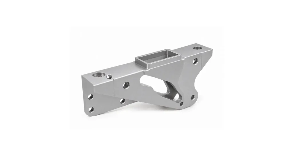
- A complex multi-sided part run on a VMC may require repeated setups and resultant cumulative tolerance errors.
- A geometrically simple part run on an HMC may incur burdens in fixtureing and cost.
Understanding the difference allows designers and sourcing teams to evaluate whether a supplier is producing a part with optimal efficiency and/or quality – or tasking equipment based on availability.
Key takeaways
- The significant and easily observed difference between VMC and HMC setups is spindle orientation: vertical or horizontal spindle orientation, with all of the consequent layout and operational differentials.
- HMC spindle utilization commonly approaches ~85%, versus roughly ~25% for many VMC production environments. This is largely a result of HMCs being better adapted to tombstone-mounted pallet changers (and to larger pallets). This allows setup to be performed on one pallet, while machining continues on the other.
- A multi-sided part that may require seven or more setups on a VMC can often be completed in two setups on an HMC using a form of tombstone fixture and a rotary table.
- VMCs are generally ideal for prototypes, simple/prismatic geometry, and low-to-medium production volumes, while UHMCs excel in multi-sided machining, high-volume production, and are well adapted to lights-out manufacturing..
What is a vertical machining center (VMC)?
A basic 3 axis VMC is a CNC machining center with the spindle axis vertical. The cutting tool presents its ‘end’ face to the top of the workpiece, and a Z axis traverse cuts a vertical cylindrical path.
The workpiece sits on a horizontal table beneath the spindle. Typically:
- the table moves in X and Y,
- the spindle (or table, or both) moves in Z.
This is the most common CNC milling configuration worldwide because it is:
- relatively affordable,
- versatile,
- easy to program,
- and well suited to general-purpose machining.
VMCs are heavily used for:
- prototype work,
- mold/die functional and cavity cutting,
- tooling,
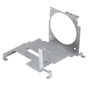
- plates and brackets,
- fixtures,
- pockets and drilling,
- general milling operations.
Their accessibility and relatively low capital cost make them the default machine platform for jobbing shops.
However, because the workpiece sits horizontally beneath the cutter, chips naturally accumulate on the surface during machining. Chip extraction therefore becomes one of the characteristic limitations of the VMC platform, for deep-pocket or high-volume work.

What is a horizontal machining center (HMC)?
It is critical to note that horizontal machining centers exist in two very different formats that have quite divergent applicability. The types are termed plain horizontal machining center (HMC) and universal horizontal machining center (UHMC).

This discussion does not apply to both types – the high flexibility system is the UNIVERSAL type, discussed hereafter.
A universal horizontal machining center (UHMC) is most commonly a 3.5 or 4 axis setup. It is a CNC machining center in which the spindle axis is horizontal, typically running from the back to the front of the machine. The cutting tool approaches the workpieces mounted to a rotary table tombstone setup.
For clarity, a 3.5 axis machine has an indexing rotary table that presents a part in a fixed orientation and can index position to present the next part. a 4 axis machine allows dynamic rotational positioning of the part, to increase access for complex cutting.
The workpiece is usually mounted in:
- a tombstone fixture, mounted to a rotary table
- on a pallet,
The 4th axis is an automated rotary table, rotating the fixtured part around a B axis, allowing multiple sides of the part to be presented to the spindle as part of the programmed toolpath.
Most UHMCs integrate pallet changers, enabling one pre-prepared pallet to be loaded or unloaded, while machining continues on another.
This dramatically increases spindle utilization because the spindle spends far less time idle during load/unload events.
UHMCs are especially effective for:
- multi-sided parts,
- production machining,
- automotive components,
- hydraulic manifolds,
- aerospace housings,
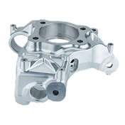
- castings,
- deep cavity work,
- lights-out production.
The horizontal orientation also allows gravity-assisted chip evacuation in most process stages, which significantly improves tool life and process stability during heavy material removal.

VMC vs UHMC: Spindle orientation and cutting direction
Spindle orientation is the defining architectural difference between VMCs and UHMCs, and it defines most operational consequences in equipment applicability.
VMC orientation
In a VMC, pockets and channels are generally upward facing when cut. Z axis cuts utilize the end facets of tools, X and Y traverse therefore uses the peripheral cutter edges.
This has consequences that can have a significant bearing on the machining process:
- chips remain on the workpiece, filling up the upward facing cavities and pooling on the part, held in place by gravity,
- coolant must be used to clear chips actively, as well as reduce part/cutter heat buildup,
- deep pockets can trap chips that coolant flow is not reliably able to clear,
- repeated recutting of these residues increases heat and wear and degrades surface finish.

UHMC orientation
In an UHMC, the spindle runs horizontally, the machining faces of a cutter rotate horizontally, and tools present towards the machine front.
This also imposes consequences in the machining process that must be considered and accommodated or exploited:
- chips from face-cutting on the sides of a workpiece fall away naturally,
- this results in generally less chip recutting, better thermal stability, and better surface finish consistency,
- this can also deliver improved tool life.
- In trench or pocket cutting on the top of a workpiece, chip entrapment in upward facing pockets remains an issue.
This profound structural difference is a driving reason why UHMCs dominate in high-volume production machining.

Workholding and multi-sided machining
The number of setups required to complete a part is often the single biggest driver of cost and precision differentials between VMC and UHMC machining.
Every setup introduces:
- labor,
- fixture time,
- alignment error,
- tolerance stack-up risk,
- and inspection overhead.
Multi-sided parts on an VMC
A six-sided component on a VMC may require:
- manual repositioning,
- multiple vises,
- angle plates,
- custom fixtures,
- repeated datum re-establishment.
A moderately complex housing may require:
- 6 to 8 setups,
- repeated edge finding,
- and cumulative error introduction
Multi-sided parts on an UHMC
An UHMC often uses a tombstone fixturing, which, combined with the 4th axis rotary table (B axis) allows:
- multiple parts,
- multiple orientations,
- automatic indexing,
- reduced manual intervention.
A part requiring seven VMC setups may require only one primary setup, plus precision pallet loading (offline, while production continues).
This dramatically reduces:
- tolerance stack-up,
- handling time,
- labor cost,
- and production variability.
It is noteworthy that, in some cases, the VMC advantage over an UHMC setup is primarily a result of the more common 4th axis, rather than the often presumed tool axis orientation.
Chip evacuation in VMC vs UHMC
Chip evacuation is not a secondary consideration. It directly influences:
- tool life,
- thermal stability,
- surface finish,
- spindle load,
- and cycle time.
VMC chip management
In a VMC, more of the machining typically takes place on the top (upward) face of the workpiece. This results in:
- chips falling onto the workpiece and staying put,
- pockets collecting chips,
- increased coolant flows to try to flush chips actively,
- recutting becomes common.
Recutting chips causes heat buildup, tool wear, degraded finish, and dimensional inconsistency in extreme cases.
This becomes especially problematic in:
- deep cavities,
- Aluminum roughing,
- high-speed machining,
- and heavy material removal roughing operations.
UHMC chip management
In an UHMC, when much of the active cutting takes place on the vertical sides of the workpiece:
- gravity assists evacuation, so chips fall away from the cut zone,
- coolant clears chips more effectively,
- deep cavities stay cleaner.
The result of this gravity-assisted clearance of cuttings us:
- longer tool life,
- more stable cutting,
- improved suitability for unattended and lights-out machining,
- reduced thermal distortion.
This is why UHMCs generally excel in:
- heavy material removal,
- cast Iron machining (aggressive chips),
- large production runs,
- and lights-out machining.
Productivity and cycle time: VMC vs UHMC
The productivity difference between VMCs and UHMCs is not primarily about spindle speed or feedrate.
It is about how much time the spindle spends cutting, which directly results from increased palletization and the reduced setups that result from the 4th (B) axis.
VMC utilization
Typical, low palletization and 3 axis VMC environments involve greatly increased:
- loading pauses,
- setup pauses,
- manual repositioning,
- manual chip clearing,
- complexity of fixturing.
Real-world spindle utilization averages around 25-35%, even in the best shops.
UHMC utilization
UHMC pallet changers allow one pallet to load, while another machines.
When combined with:
- the 4th (B) axis rotary table
- tombstone and pallet fixturing,
- heavy investment in automation,
- superior chip evacuation,
- real-world spindle utilization often approaches 85%.
This is why one (automated load/unload, 4 axis) UHMC can potentially replace several (low automation, 3 axis) VMCs in production output.
What is the cost difference between VMC and UHMC?
VMCs generally cost less to purchase, while UHMCs often produce lower cost per part at scale. Some of this differential relates to the generally more robust construction and higher power prevalent in UHMCs. And the very common presence of the 4th axis in UHMCs.
The correct selection of equipment to produce a part depends on planned production volume, part geometry having greater suitability for one format, and the setup complexity required to achieve rigidity and precision..
Initial purchase price
Approximate ranges:
| Machine Type | Typical Price Range |
|---|---|
| VMC | $50k to $300k+ |
| UHMC | $250k to $1M+ |
For the elevated productivity they are typically reputed to offer, UHMCs require:
- pallet systems,
- tombstone fixturing,
- rotary tables,
- larger enclosures,
- more sophisticated automation.

It is no surprise that heavier grade, more capable, and better equipped solutions cost more than lighter, simpler, but more adaptive machines.
Floor space, setup, and tooling costs
UHMCs are big machines, often with ancillary equipment, andvttey typically require:
- larger footprints,
- more complex fixtures,
- higher tooling investment.
However, once that investment is made, they reduce:
- labor,
- setups,
- handling,
- idle spindle time.
Cost per part at different volumes
| Volume | VMC Cost Profile | UHMC Cost Profile |
|---|---|---|
| 1–50 | Low setup investment | Fixture cost hard to amortize |
| 50–500 | Setup cost grows significantly | UHMC efficiency improves |
| 500+ | Labor/setup dominate | Low cost per part |
| 5,000+ | Rarely competitive for complex parts | Strong UHMC advantage |
The crossover point depends heavily on:
- number of setups,
- automation level,
- fixture complexity,
- cycle time.
Applications: Should you choose VMC or UHMC for your part?
The correct selection of machining center for a particular task depends on:
- part geometry,
- part size
- number of required setups (and influence of resulting datum degradation),
- volume of product required,
- and overall production strategy.
When to choose a VMC
VMCs are ideal for:
- prototype and low volume work,
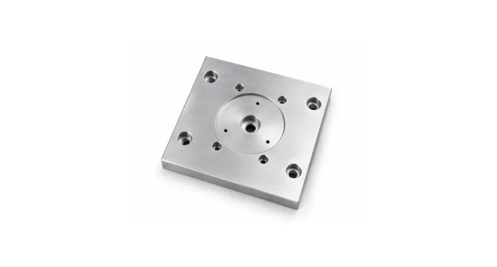
- mold plates with extensive main-face machining resulting in single or at most double setup,
- flat, prismatic parts,
- simple geometry,
- low-to-medium production volume
VMC machining setups excel when:
- flexibility matters,
- fixture simplicity is imperative to restrain setup costs,
- capital cost matters,
- or setups are minimal.
When to choose a UHMC
UHMCs excel for:
- multi-sided parts,
- deep cavities,
- castings,
- hydraulic manifolds,
- aerospace housings,
- automotive production,
- lights-out machining,
- larger parts (as UHMCs tend to be larger machines)
They become economically dominant when:
- setup count is would be high, without tombstone setup and 4th axis availability,
- volume is high,
- or spindle utilization is a priority.
Tolerances, rigidity, and surface finish
Both VMCs and UHMCs can achieve similarly tight tolerances.
The difference arises not from an academic analysis of capability, but from the need for consistency across multiple and ongoing setups.
An UHMC often maintains better positional consistency because:
- fewer setups are required,
- therefore fewer datum transfers put precision at risk,
- fixturing remains stable through long jobs,
- thermal stability is typically improved by reduced cuttings buildup
On complex parts, using stiffer machines, these factors combine to dramatically reduce:
- hole positional error,
- perpendicularity variation,
- tolerance stack-up.
UHMCs also tend to perform well in heavy roughing because:
- chip evacuation improves,
- structures are typically more rigid than in VMCs,
- cutting loads remain more stable.
3-axis vs 4-axis vs 5-axis on each platform
Axis count is independent of machine orientation. Both VMCs and UHMCs can exist as:
- 3-axis,
- 3 ½ axis,
- 4-axis,
- or 5-plus axis embodiments.
However, the practical implications differ significantly, influencing repeat setup count, complex profile production, part complexity capability, and ability to be effectively automated for low supervision and lights-out operations.
VMC 5-axis
Advantages:
- excellent for complex surfacing,
- aerospace geometry,
- mold work,
- medical parts.
Limitations:
- chip evacuation challenges remain,
- large workholding can involve challenges/stability compromises
UHMC 4-axis / 5-axis
Advantages:
- excellent multi-face access,
- high productivity and volume operational efficiency,
- fewer setups,
- highly automated workflows.
These systems dominate:
- production aerospace,
- automotive,
- high-volume industrial machining.
DFM Considerations: Designing parts for VMC or UHMC
The machine platform can influence part design. Features that are easy on an UHMC may become extremely expensive on a VMC.
Examples:
- side features requiring repeated repositioning,
- deep cavity machining,
- multi-face drilling,
- compound datum structures.
Poor machine-awareness during design often creates unnecessary:
- setup count,
- tolerance stack-up,
- fixture complexity,
- labor cost.
Good DFM questions include:
- How many setups are required?
- Can multiple faces be machined in one orientation?
- Will chips evacuate effectively?
- Does the geometry favor tombstone fixturing?
- Will repeated datum transfers accumulate error?
These decisions often determine production cost more than spindle horsepower or machine brand.
How to choose between a VMC and an UHMC
The decision process can generally be guided by answers to three questions:
Volume threshold
Low volume usually favors VMC.
High volume often favors UHMC.
Number of setups required
The more setups required, the stronger the UHMC case becomes. If the part requires:
- 6 to 8 setups,
- repeated flipping,
- or multiple datums,
UHMC economics and suitability become clear.
Available capital and floor space
Even when UHMCs are technically ideal, they may not fit the:
- budget,
- floor space,
- staffing skills matrix,
- or production strategy.
Many shops therefore use VMCs successfully for work that could theoretically favor UHMCs. Where such work is intermittent, the cost benefit sits firmly with VMCs.
How to choose a supplier with the right machines
Understanding VMC vs UHMC selection processes only matters if the engineer uses that knowledge to evaluate suppliers rigorously.
A supplier machining a complex multi-sided part on a VMC is not necessarily unaware of the relative benefits of UHMCs, but may have strong commercial or investment drivers encouraging acceptance that:
- the setup count may be high,
- tolerance risk rises,
- cycle time grows,
- labor increases,
- and cost per part climbs.
Important supplier-investigation questions include:
- How many setups are required for my part?
- What machine platform will be used?
- Is the part appropriate for tombstone?
- Is pallet automation available/relevant?
- How is datum transfer controlled?
- Will the part run lights-out?
- How is chip evacuation handled?
- What is the in-house spindle utilization target?
These conversations frequently reveal whether the supplier optimized their process, or merely found a way to make the part possible within their existing setup.
This is especially important during:
- scaling from prototype to production,
- aerospace qualification,
- tight-tolerance production,
- and high-volume manufacturing.
Conclusion
VMCs and UHMCs are optimized for different manufacturing realities.
- VMCs excel in prototype work, simple geometry, tooling, mold plates, and lower production volumes where flexibility and lower capital cost matter most.
- UHMCs excel in multi-sided machining, high-volume production, deep cavity work, and automated lights-out manufacturing where spindle utilization and reduced setup count dominate economics.
The productivity gap between the platforms compounds exponentially at scale – one UHMC can routinely match the output of several VMCs on the most appropriate type of work.
For engineers sourcing machined parts, the practical question is simple: does your supplier have the right machine for your geometry, volume, and tolerance requirements?
Frequently Asked Questions
When does it make financial sense to move apart from a VMC to an UHMC?
The transition usually becomes economically attractive when:
- setup count becomes high,
- production volume increases beyond a critical threshold,
- or spindle idle time dominates cost.
Multi-sided parts above moderate production volumes often cross over into UHMC advantage surprisingly quickly.
What questions should you ask a CNC supplier about their machining setup?
Important questions include:
- What machine type will run the part?
- How many setups are required?
- Will tombstone fixturing be used?
- Is pallet automation available?
- How are tolerances maintained across setups?
- Is the process optimized for production volume or prototype flexibility?
These answers often reveal more about true production capability than the quote alone.