
Heat sinks are among the most commonly used thermal management devices. While technically passive – in that they absorb heat from a hot source and then carry it to passive cooling features – they are often actively cooled by forced air circulation, adding an active element to their process.
They play a critical role in keeping power electronics, processors and even hard working RAM/ROM memory reliable, efficient, and in safe operation. As power densities rise and devices shrink, effective heat dissipation becomes increasingly critical in preventing the overheating that results in performance degradation, material damage, and early component failure. A heat sink absorbs heat by direct thermal coupling to a component such as a processor, power module, LED, or inverter – and dissipates that heat into the surrounding environment through a combination of conduction, convection, and radiation.
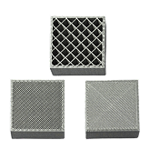
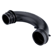
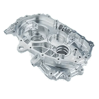
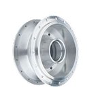
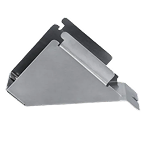
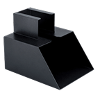
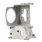
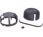
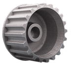
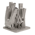
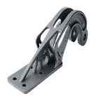
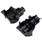
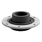
The variety of solutions in heat sinking are well illustrated in the following figures, in order of increasing effectiveness:


Key takeaways
- Heat sinks are essentially passive thermal devices that conduct heat away from electronic or mechanical components and dissipate it into the environment.
- A heat sink works by combining conduction (from the component), convection (to air), and radiation (to ambient surfaces).
- Material selection – typically Aluminum or Copper for higher thermal stress applications – material significantly affects thermal conductivity, weight, cost, and manufacturability.
- Heat sink design depends on fin geometry, surface area, thermal resistance, airflow, and base thickness.
- Manufacturing methods – including extrusion and from-solid machining to skiving and die casting – strongly influence performance, complexity, and cost.
Heat sink definition: Understanding thermal management devices
A heat sink is typically a passive component, but in some cases active cooling means are applied to enhance thermal performance. They are designed to manage and dissipate unwanted heat generated by electronic or mechanical systems. This is essential in a wide range of applications, because nearly all electronic components – processors, power transistors, LEDs, memory modules, FETs, and many mechanical systems – convert part of their process energy (electrical, kinetic, chemical) energy into heat.
Without a means of dissipating heat, many electronic components would exceed their junction temperature limits; and many non-electronic systems would exceed their optimum reaction, lubrication or material stability limits. This can result in operational disturbances, material degradation or catastrophic component damage.
The purpose of a heat sink is simple:
- Absorb heat from a source with high thermal density.
- Spread the heat across a larger surface area or mass/volume to lower the contact temperature.
- Dissipate the heat to the surrounding air or coolant.
Heat sinks are engineered to minimize thermal resistance, which arises from various sources:
- From the component to the heat sink (thermal interface material (TIM) and material junction resistances)
- Through the heat sink body (conduction resistance)
- From the heat sink to the air or fluid surround, or coolant fluid in internal channels (convection resistance)
Key components of a heat sink system
A very wide range of formats and constructions of heat sink assembly are used, but at an element level they can generally be described in schematic ways that typically include:

- Base plate – provides thermal spreading
- Fins or pins – increase surface area
- Thermal interface material (TIM) – reduces interface resistance
- Mounting hardware – clips, screws, adhesives
- Various functional enhancements offer active or forced heat dissipation – heat pipes, vapor chambers, fans with or without flow control cowlings
How does a heat sink work?
Heat sinks operate based on three core heat transfer mechanisms, the relative importance of which varies considerably with application context, heat sink design/operation and ambient environment. Emphasis on one or more of these heat loss/dissipation mechanisms is a clear design intent and significantly affects the potential complexity and cost of a component.

Conduction
Heat moves from the component (e.g., CPU, MOSFET, IGBT, gearbox lubricant, chemical reaction chamber, combustion chamber wall) into the heat sink base through physical/thermal coupling means such as a TIM layer; or by direct integration of the heat sink elements as part of a the heat-source containment/walls. Aluminum and Copper are used because of their relatively high thermal conductivity, to encourage this initial capture and the conductive transfer to the passive or active cooling features.
Convection
Once heat reaches the passive heat dissipation surfaces (fins) or active cooling means (heat pipes, fluid galleries etc), it transfers to the surrounding air/water/oil etc or to the more active coolant process integrated into the design.
- In natural convection, air movement occurs without mechanical assistance.
- In forced convection, fans or blowers significantly improve heat transfer rates.
In actively cooled heat sinks, heat is transferred to heat pipes that carry it away more effectively – or it is transferred to a coolant fluid that is pumped or convectively/thermally/gravitationally circulated to a separate cooling position, which is at a lower ambient temperature or is less space constrained.
Radiation
All surfaces emit thermal radiation. Black anodized surfaces help improve radiative heat loss, though it contributes less than convection and conduction.
The potential rate of heat dissipation depends heavily on the ambient temperature of material (or space) around the heat sink. Black body radiation to a same-temperature surrounding is net zero, as heat ‘circulates’ in both directions.
Types of heat sinks
Heat sinks can be categorized by cooling method, structural design, or manufacturing technique. A huge variety of features are type-illustrated in Fis 1-4 above.
Passive Heat Sinks
- Operate without fans
- Rely entirely on natural convection
- Ideal for low-noise, low-power or sealed systems
- Common in consumer electronics, lighting, and embedded systems
Active (air cooled) heat sinks
- Include fans or blowers to boost airflow
- Handle higher power densities
- Used in CPUs, GPUs, power systems, industrial controls
Liquid-cooled heat sinks
- Use coolant channels to remove high heat loads
- Employed in EV inverters, power electronics, lasers, telecom infrastructure
Active (heat pipe or liquid cooled) heat sinks
- Incorporate pipes that use phase-change technology to spread heat; or coolant flow channels that allow active cooling at a point away from the heat source
- Excellent for tight spaces and uneven heat loads
- Heat pipes are common in laptops, 5G radios, advanced computing systems; Fluid cooled heat sinks are common in high power electronics, in EV battery temperature control and in aerospace applications.
Stamped vs extruded vs machined vs skived heat sinks
| Method | Cooling Capacity | Complexity | Cost | Common Applications |
|---|---|---|---|---|
| Stamped | Low | Low | Very low | Consumer devices, simple electronics |
| Extruded | Medium | Medium | Low | Power electronics, industrial, general-purpose aluminium heat sinks |
| CNC Machined | High | High | High | Custom heat sinks, tight-tolerance applications |
| Skived | Very high | High | Medium-high | High-performance CPUs, server power systems |
| Bonded Fin | Very high | Medium | Medium | High airflow environments, power modules |
Common applications of heat sinks
Heat sinks appear in almost every sector where electronics are used.
Consumer electronics
- Smartphones
- Laptops
- Gaming consoles
- Smart home devices
Typical heat sinks: small stamped metal or graphite-based components.
Computer hardware
- CPUs and GPUs
- VRMs and chipsets
- SSD controllers
Typically these are heat pipes, combined with extruded or vapor chamber heat sinks.
LED lighting
LEDs generate concentrated heat at the junction. Since lighting is often fanless, large (extruded or stamped metal) passive Aluminum heat sinks are standard.
Power electronics
- IGBTs
- MOSFET arrays
- Inverters
- DC-DC converters
Commonly these employ extruded or bonded fin Aluminum heat sinks.
Automotive electronics
- Battery management systems
- Motor controllers
- ADAS modules
- Air cooled engine and gearbox parts

In many cases these stray into liquid cold and active devices that sit on the boundary between heat-sinks and heat-exchangers. They use either heat-pipes (for lower temperature differential and more steady heat applications) or active coolant circulation for more extreme heat or temperature variability applications.
Industrial equipment
- Robotics
- VFDs
- PLCs
- Drives and converters
This is a broad context that ranges from simple power electronics requiring fin-based heat dissipation by convection; through gearbox cooling by passive fins and/or lubricant circulation; to active cooling of combustion and reaction chambers where the thermal challenges can be considerable.
Telecommunications
- 5G radio units
- Antenna modules
- Power amplifiers
Telecoms heat sink solutions also cover a wide range, from active cooling of microwave antennas, to passive cooling of laser signal boosters in long-line fiber-optic connections.
Applications
| Application | Typical Dissipation | Common Heat Sink Type |
|---|---|---|
| CPUs/GPUs | 50–200 W | Heat pipe + fin stack |
| LED modules | 5–50 W | Passive aluminium heat sinks |
| Power inverters | 100–600 W | Extruded/bonded fin |
| EV power modules | 500–3000 W | Liquid-cooled cold plates |
| Telecom radios | 50–300 W | Cast Aluminium + heat pipes |
| Microwave antennas for long range | Potentially several kW | Liquid cooled systems of large scale, with dissociated passive (or forced air) heat dissipation systems |
Materials commonly used in heat sink fabrication
Material selection heavily influences thermal performance, weight, manufacturability, and cost. In lower power applications, the implications of the choice of materials are minimal and moderate performance can be tolerated. In high temperature, high power and large heat variability applications, the choice can be pivotal in driving following aspects of design.
Aluminum alloys (6061, 6063)
Most widely used due to:
- Good thermal conductivity (~200-220 W/m·K)
- Lightweight
- Easily extruded or machined
- Cost-effective
Use aluminum heat sinks when CNC machining is required
Copper and copper alloys
- Much higher thermal conductivity (~390-400 W/m·K)
- Ideal for bases and high hot-spot spreading
- Heavier and more expensive
- Harder to machine
Aluminum-copper composites
- Combine Aluminum’s weight with Copper’s conductivity
- Used in hybrid CPU coolers and thermal cores
Specialty materials: Graphite, ceramics
- Graphite: extremely high in-plane conductivity
- Ceramics: offer electrical insulation + good conduction
- Used in aerospace, extreme environments, or compact electronics
Material selection criteria and trade-offs
| Material | Thermal Conductivity (W/m·K) | Density | Relative Cost | Applications |
|---|---|---|---|---|
| Aluminium 6061 | 167–201 | Low | Low | Extruded heat sinks |
| Aluminium 6063 | 200–220 | Low | Low | High-fin extrusions |
| Copper C110 | 385–400 | High | High | High-performance bases |
| Graphite | 150–500 (in-plane) | Very low | Medium-high | Lightweight electronics |
| Ceramics | 10–30 | Medium | High | High-voltage, insulated applications |
Heat sink design considerations for thermal performance
Heat sink design is entirely derived from application requirements – there is no one-size-fits-all solution. Engineers/specifiers/designers must evaluate performance targets, airflow, geometry limits, and cost implications in making informed and effective choices throughout their process.
Factors influencing heat sink selection
- Power dissipation (W)
- Maximum allowable junction temperature
- Airflow (natural or forced)


Typically 70-90% of fin cooling is by convection
The boundary layer thickness (shown grey/transparent) is heavily influenced by ambient temperature – cooler air is more dense, allowing the boundary layer to be thinned by pressure from cooler ambient air sinking
The minimum convection cell (shown yellow) defines the ability of the fin to lose heat. Where the ΔT is larger (left) the minimum convection cell occurs lower down, increasing convective heat loss.
Note that the convective flow regime will vary with fin orientation. If the vertical axis lies ALONG the fins length, the boundary layers are more 3D and harder to represent graphically, but the thermally driven flow can develop greater momentum and result in stronger heat transfer to the ambient environment.
- Orientation (vertical for natural convection)
- Available space and the need for heat-pipe or liquid cooling to carry heat to a less constructed space.
- Required weight and cost
- Supply chain and technical issues in manufacture and maintenance
Fin configurations
- Straight fins – suitable for directed convection or forced airflow
- Pin fins – improved performance through improved air-flow turbulence/mixing, providing multidirectional natural convection
- Radial fins – Ideal for LED and circular housings
Optimizing fin geometry
Performance improves with:
- Higher fin density
- Larger total surface area
- Adequate spacing for airflow, with sufficient mixing to prevent poor convective heat transfer
- Typically use high aspect ratio fins under forced air flow, stubbier fins under natural convection
Base thickness and thermal spreading
A thicker base spreads heat more effectively but adds weight and cost. Copper bases are often bonded to Aluminium fin stacks, for improved hybrid performance.
Natural vs forced convection
- Natural convection requires fin spacing to be wider to allow buoyancy-driven airflow – fin height-to-gap aspect ratio is between 3:1 and 5:1
- Forced air circulation allows denser fin packing, thinner walls, taller fin stacks. height-to-gap aspect ratio typically between 1:3 and 1:8
Heat pipe integration
Heat pipes, circulated coolant or vapor chambers dramatically improve spreading efficiency for uneven heat loads or compact form factors. These are typically used to move heat to a less thermally constricted or space-limited area, to allow dissociated passive or active cooling elements to be more effective than in close proximity to the heat source.
Common manufacturing processes for heat sinks
Various manufacturing processes yield divergent performance outcomes, costs, and design constraints in delivering effective solutions.
Extrusion
- Most common
- Ideal for Aluminum
- Medium cost of setup/tooling, good thermal performance, only suited to medium to high volume manufacture – extrusion is typically performed/costed by the tonne.
- Typical fin heights lie in the range 10 to 60 mm
Die casting
- Allows complex shapes and mounting features
- Lower conductivity due to alloy composition and the crystalline structure of the cast material
- Used in automotive and telecom housings
- Requires high cost of setup/tooling but allows close coupling and complex shapes for highly specific applications
CNC machining
- Excellent precision
- Ideal for custom (one-off and low-volume) heat sinks
- Higher cost, slower production
- Useful for prototypes or complex geometries
Stamping and forging
- Medium to high-volume production
- Good for small consumer devices
- Limited thermal performance
- Low cost per device, moderate setup/tooling costs
Bonded fin construction
- Allows very high fin density
- Excellent for forced-air systems
- Considerably more expensive than extrusion, reserved for high value applications
Advanced and secondary processes
- Skiving – produces extremely thin, high-performance fins
- Vapor chambers & heat pipes for spreading
- Surface treatments such as anodizing improve radiation
- Post-processing such as precision milling ensures flatness
Custom heat sinks: When and why to go custom
Benefits
- Optimized thermal performance for specific power loads
- Exact fit for mechanical space constraints
- Ability to integrate mounting holes, pipes, ducts, or interface features
Why choose to customize
- Off-the-shelf heat sinks fail thermal simulations
- High-volume manufacturing requires cost optimization
- Space constraints prevent using a standard extrusion
- Complex airflow conditions require custom fin geometry
Design considerations
- Target thermal resistance
- Assembly requirements
- TIM selection
- Manufacturability and cost
- Prototype iteration cycles
Prototyping and production volumes
CNC machining is typical for prototypes; extrusion or die casting is used for scale. The tooling and production setup costs for higher volume processes preclude their use in lower volume applications.
Recent trends and innovations in heat sink design
Additive manufacturing
3D printing removes most of the how-to-make design constraints, allowing optimized solutions that are limited by material type and thermal performance issues only. The use of lattice structures for improved heat transfer/fluid turbulence; internal and un-machinable channels for complex and optimized fluid flow; and high surface to volume ratio structures are all unlocked by the move to additive processes.
However, process selection for the printing stage is critical, as not all additive processes are ideal for optimization of thermal conductivity, which can counteract the design benefits
Phase-change materials
Help reduce thermal spikes and smooth load transitions. These add thermal capacity to the heat sink, dissipating the heat-input into the latent heat of liquefaction or vaporization, enabling the buffering of brief high-heat episodes, when post heat cooling can be slower.
Microchannel and vapor chamber technologies
Improve heat spreading and coolant flow efficiency. Transfer of heat from the metal/graphite structure into an intermediate working fluid (liquid or vapor) can greatly boost heat transfer away from critical areas. This then allows a less aggressive convection/radiation process to take place at a site remote from the heat course, reducing space and ambient temperature constraints on system performance.
Graphene and advanced TIMs
Ultra-high conductivity materials reduce interface resistance. While these can impose manufacturing and application challenges, the performance enhancement can be of overwhelming value in some high-tech applications.
AI-driven thermal optimization
Machine learning can assist in optimizing fin geometry and predict hot spots. It can also allow more unusual solutions and the integration of wider learning than an individual designer might have time or patience to explore.
Sustainable designs
Recyclable Aluminum and low-energy manufacturing processes are becoming increasingly common. At their heart, heat exchangers of the simplest type are highly recyclable. Composited materials and integrated heat pipes typically pose challenges that make basic recycling not cost-effective, however.
Summary
Heat sinks are essential thermal management devices that protect electronic systems from overheating by conducting, spreading, and dissipating heat. Selecting the right heat sink involves understanding materials, design parameters, manufacturing methods, airflow conditions, and application requirements.
Whether your project requires a standard extrusion or a custom heat sink, platforms like Jiga help engineers source, compare, and manufacture high-quality heat sinks with fast turnaround.