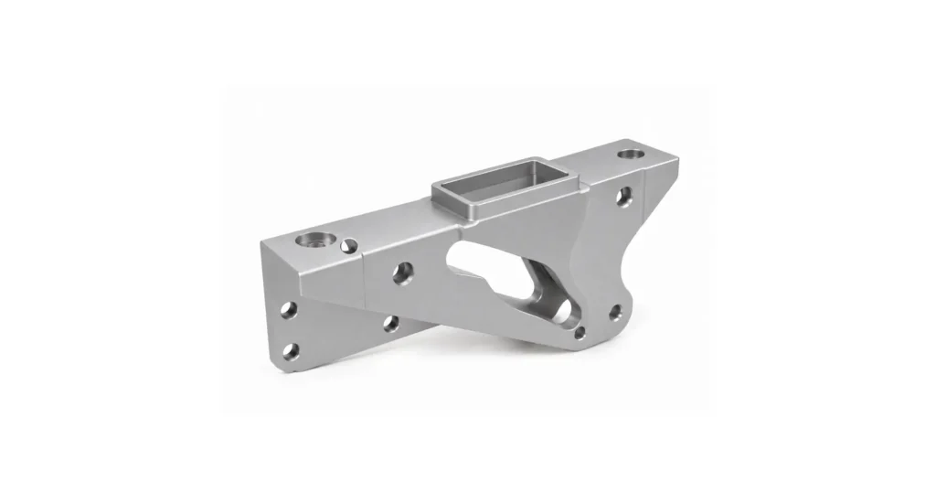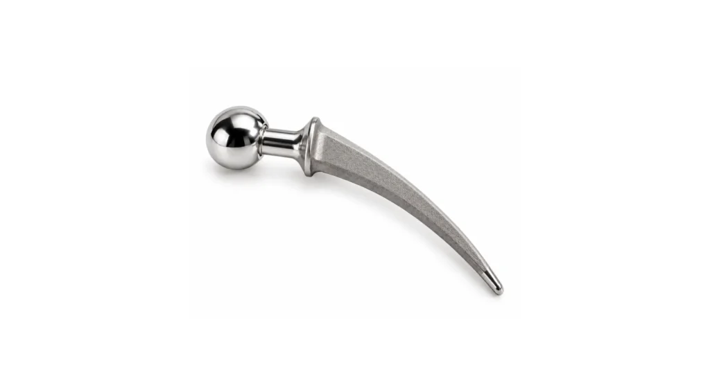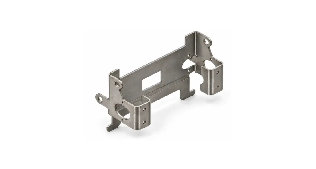
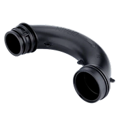
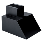
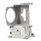
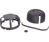
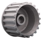
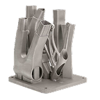
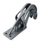
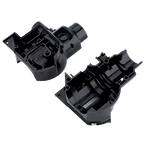
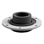

CNC machining for plastic parts is a group of subtractive manufacturing processes that typically use computer-controlled rotating cutting tools (milling), or static cutters (turning), and linear, rotational, or complex motion of the cutter and workpiece to remove material. In this way, the required part is extracted from the solid plastic stock to produce precision components. It is widely applied by engineers sourcing prototypes and low-to-medium volume production parts, where required tolerances, material performance, and repeatability fit the achievable profile of the process.
Unlike in the case of molding or additive manufacture, CNC machining delivers approximately production-grade materials with tight dimensional control – provided the process is adapted to the characteristic behaviours of plastics.
High strength material alternatives to CNC machining are not plentiful. Selective laser sintering can deliver nylon and polypropylene with good accuracy, but a granular finish; rapid (soft) tooling can use most thermoplastic materials, but the cost is high; vacuum casting can mold thermoset simulants of thermoplastics and elastomers, with some loss of accuracy as the final parts are second generation reproductions of additive manufactured primaries, via silicone immersion cast molding cavities.
None offers the combination of material breadth, precision, rapid turnaround, and adaptability of CNC machining of plastics.
Key takeaways
- CNC plastic machining enables tight tolerances on engineering-grade thermoplastics and high-performance polymers.
- Plastics behave fundamentally differently from metals – heat, chip evacuation, and tool sharpness are high sensitivity issues.
- The process is often ideal (depending on component features and details) for prototypes and low-to-medium production runs, without tooling investment or schedule bloat.
- Material selection directly affects machinability, stability, and cost.
- Supplier capability – especially DFM and material experience – determines final part quality.
What is CNC plastic machining?
CNC plastic machining is the subtractive extraction of a part from a solid, whereby material is removed from plastic billets or sheets using computer-controlled cutting tools such as mills, lathes, and routers. Toolpaths are generated from CAD models and executed with high precision.
Unlike injection molding, which requires dedicated tooling and is optimised for high volumes, CNC machining produces parts directly from stock, with no upfront tooling cost other than, possibly, on-machine jigs and part retainers. Compared to 3D printing, CNC machining delivers superior dimensional accuracy, surface finish, and full-density material properties.
It is worth noting that the characteristics of CNC machined plastic parts can differ considerably from molded equivalents.
- Firstly, thin sections and features with limited support can be molded with relative ease, but represent significant challenges in CNC machining, with flexible materials.
- Secondly, while materials may be class-representative of intended manufacture, the fine details of grade and additives are likely to differ – often markedly.
- Thirdly, local properties rarely match those of the eventual molded component, as the mold filling process typically imposes flow structures analogous to grain. This can be explored and controlled in tool design and flow planning in ways not available through extractive processes.
These factors can represent a significant expectation barrier and require careful preparation by a development team, in the minds of stakeholders.
For parts that must bear load, maintain tight fits, or operate in thermal or chemical environments, CNC machining is nonetheless typically the preferred method.
How CNC plastic machining works
The process follows a structured workflow from digital design to finished part.
Step 1: CAD model and file preparation
Engineers export a 3D model (typically native CAD data, STEP or IGES formats) with drawing defined tolerances and surface finish requirements. These specifications directly influence machining strategy and cost.
While ‘quick look’ prototypes can be performed purely from CAD data, CNC machined parts often require careful interrelationship with each other, making careful tolerance control a necessary step. This can only be achieved through provision of 2D annotated part drawings – and it will also benefit from use of assembly drawings or 3D models to equip the CNC programmer with a clear understanding of the component fits and interactions.
Step 2: CAM toolpath programming
The supplier imports the model into CAM software and generates toolpaths in G-code, referencing the secondary design information in 2D drawings and assembly drawings/models.
For plastics, feeds and speeds are moderated to prevent melting, reduce burr formation, and maintain chip evacuation. Tool selection – often O-flute or polished cutters – is critical in achieving accuracy and surface finish of required standards. The need for finishing cuts directly results from surface finish and tolerance needs, which must be integrated at this stage.
Step 3: Material preparation and setup
Plastic stock is selected according to a range of criteria, and secured using fixtures or vacuum tables. Compared with metal part machining, plastics are low rigidity and more fatigue-prone, making adaptive and well considered fixturing strategy and cut depth moderation essential in preventing excessive vibration or distortion during cutting.
It is typically necessary to source stress-relieved material billets, where extensive cutting and fine sections are required, as residual stresses can result in harmful local and overall distortion.
Step 4: Machining
The CNC machine executes the programmed toolpaths, extracting the net-shape of the part in a sequence of coarse, and increasingly fine cuts, their sequence being derived from a matrix evaluation of feature stiffness and aspect ratio, material rigidity, precision required and surface finish needs. Unlike metals, plastics can; easily distort under excess cutter load; and soften, warp, or smear if heat builds up. Elevated cutter rotation speeds and feed rates, shallow cuts, sharp tools, and air or mist cooling are used to keep heat in the chip rather than the part.
Step 5: Post-processing and inspection
Parts must be deburred, cleaned, and inspected. For production/assembly-intent components, suppliers may need to provide dimensional reports and material certifications.
Where higher cosmetic requirements apply, hand finishing and, in some cases, flame or solvent polishing may be used – though these can considerably increase costs and influence dimensional precision in some areas.
Tooling and cutting strategy for plastics
Plastic machining is far-removed from metal machining with softer material. Tooling strategy must be adapted:
- O-flute end mills improve chip evacuation and reduce heat buildup.
- High spindle speed + high feed rate prevents rubbing and melting.
- Sharp tools are a MUST have; dull tools create displacement and distortion and generate heat while failing to cut.
- Air blast or mist cooling is often preferred over flood coolant.
- Non-aggressive cut depths are typically used to reduce the friction heating.
Poor cutting strategy or inadequate or design-insensitive toolpath strategies are the most common causes of dimensional inaccuracy and surface defects in plastic parts.
Common CNC operations for plastic parts
CNC milling
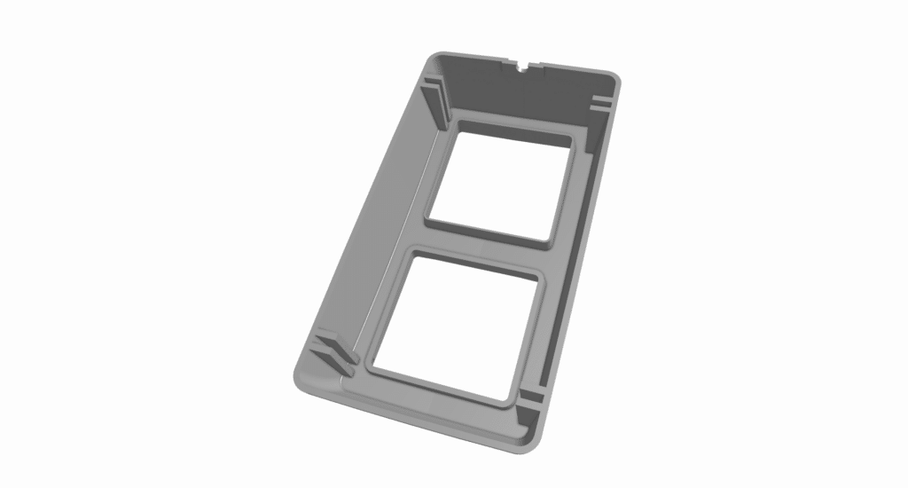
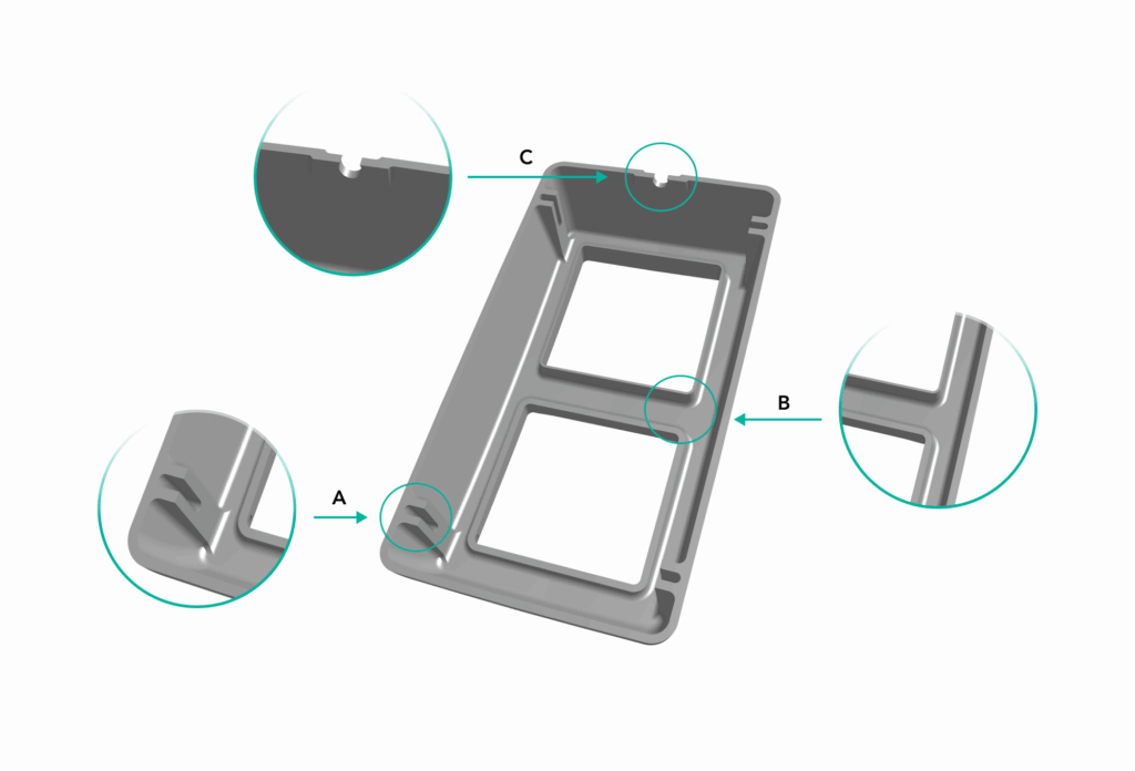
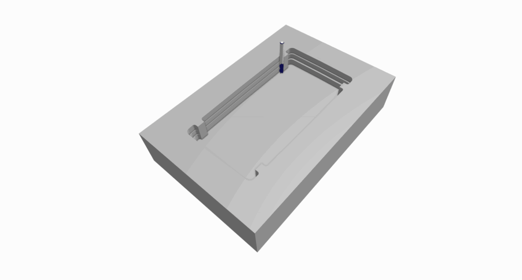
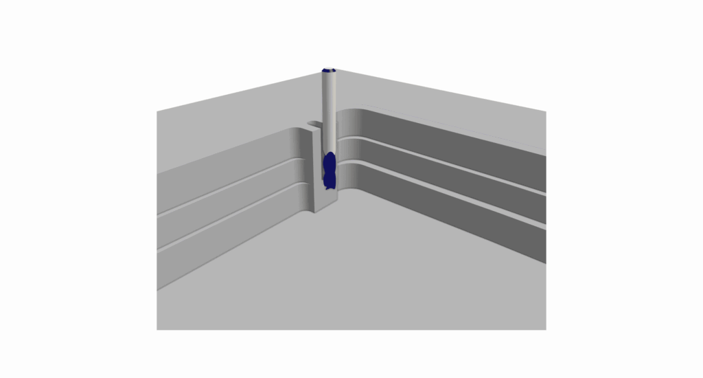
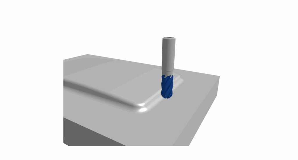
Milling removes surface material by passing rotating tools over the billet (by a combination of cutter and work piece motion), to extract 3D features such as pockets, slots, and contours. It is a highly versatile operation-class and is used for the majority of plastic components. The complexity of CNC milling equipment (3 axis, 4 axis, 5+ axis) is driven by the nature of the design – compound curvatures and the need for 5 or 6 face access will inform the programmer/machinist as to the right choices. This often results from a balanced analysis of the cost-per-hour of equipment against the cost of fixturing, and the accuracy loss of repositioning to allow better access.
CNC turning
Turning rotates the workpiece and presents stabilized, single point cutting tools, on or off axis drills and other specialist live and stationary cutting tools, on more complex equipment. CNC turning is ideal for cylindrical parts such as bushings, spacers, and threaded fittings. Materials like acetal and nylon machine particularly well in turning operations, delivering very high precision outcomes.
CNC Routing
Routing is used for sheet-based plastics at high spindle speeds, commonly for relatively shallow cuts, made on panels, enclosures, and signage in materials such as acrylic and polycarbonate.
Drilling and tapping
Drilling and tapping are used for holes, with and without threads. Thread-forming taps are often preferred in plastics to; avoid chip accumulation; minimise re-melting and scoring inside threads; and deliver higher quality and stronger threads. Threads tend to be of moderate to low pull-out strength due to the intrinsic nature of the materials
Best plastics for CNC machining
Material selection determines not just performance, but machinability, cost, and dimensional stability.
Quick material selection guide
| Requirement | Recommended Material |
|---|---|
| Low friction, precision parts | Acetal (Delrin) |
| High temperature resistance | PEEK / Ultem |
| Optical clarity | Acrylic / Polycarbonate |
| Chemical resistance | PTFE |
| Toughness and wear resistance | Nylon |
Polymer properties comparison table
| Material | Machinability | Strength | Heat Resistance | Applications | Cost |
|---|---|---|---|---|---|
| ABS | Good | Medium | ~80°C | Housings, prototypes | Low |
| Acetal (Delrin) | Excellent | High | ~100°C | Precision parts, gears | Low |
| Polycarbonate | Moderate | High | ~120°C | Impact-resistant parts | Medium |
| Nylon | Good | High | ~120°C | Wear parts, bushings | Low |
| Acrylic (PMMA) | Moderate | Low | ~90°C | Optical components | Low |
| PEEK | Difficult | Very high | ~250°C | Aerospace, medical | High |
| Ultem (PEI) | Moderate | High | ~170°C | Electrical, aerospace | High |
| PTFE (Teflon) | Difficult | Low | ~260°C | Seals, chemical parts | High |
Key material notes
- ABS: Easy to machine but prone to melting if tools are not sharp. Moderate strength and rigidity, capable of high cosmetic finishes with extreme machining care and acetone vapor polishing.
- Acetal (Delrin, POM): Excellent machining properties, chemical resilience, thermal and dimensional stability and low friction. Delivers good engineering and structural performance, but poor cosmetics.
- Nylon: Good machining properties. Some grades absorb moisture, affecting tolerances over time. Most gtades tolerate high operating temperatures and offer good chemical resilience. Nylons offer greater engineering performance but poor cosmetic quality.
- PEEK: Machining PEEK delivers exceptional strength, chemical resistance, and thermal stability, but requires careful tooling and speeds to prevent surface tearing, ensuring tight tolerances and high-quality cosmetic finishes.
- PTFE: Very soft, prone to deformation and creep, in the homopolymer form, nak8bg machining tricky. However, the thermal and chemical resilience naje this a necessary material choice at times. Perfluoroalkoxy (PFA) offers similar resilience but easier machining.
When carefully executed with good materials and process knowledge, CNC machining can achieve tight tolerances – typically ±0.025 mm or better – while maintaining repeatability within and between production runs. Unlike additive methods, it uses full-density engineering materials, with anisotropic properties, allowing accurate functional testing under real operating conditions.
The absence of tooling makes it ideal for low-to-medium volumes, where injection molding would be cost-prohibitive. Engineers can iterate designs rapidly, receiving updated parts in days rather than weeks.
The process also supports complex geometries and a wide range of materials, including high-performance polymers that are unavailable in most 3D printing systems.
When to choose CNC machining for plastic parts
CNC machining is the preferred choice when:
- Functional prototypes must use real production materials for realistic evaluation of some aspects.
- Tolerances tighter than ±0.05 mm are required.
- Parts must interface with other components (fits, seals, bearings).
- Volumes are below ~1,000 units.
- Design iteration is ongoing.
- Regulatory validation requires production-intent materials.
In many applications, CNC machining is not a bridge to molding – it is the final production method. A combination of low required volume and moderate to high per-part price sensitivity can leave limited options, other than this.
Industries and applications
Medical devices
CNC machining of medical components supports clinical trial volumes using materials like PEEK and polycarbonate. It enables tight tolerances, traceability, and high-quality surface finishes for fluid-path and surgical components. It also serves in patient-custom applications, where individual parts are required and tooling costs are unsupportable.
Aerospace
Lightweight, high-performance plastics such as Ultem and PEEK are machined for structural and thermal applications where metals are not appropriate for chemical, friction, or weight reasons. Jiga is highly active in this area.
Electronics and industrial
Common applications include enclosures, insulators, bushings/grommets, and wear components where dimensional stability and repeatability are critical. In particular, ABS is widely used in enclosures for sensors, controls, handheld devices, weather shields, and wearable devices. It offers a good balance between toughness/resilience and good cosmetics.
Prototyping and functional testing
CNC machining allows engineers to validate designs using close-to actual production materials rather than additive manufactured approximations that poorly represent a wide range of real-material properties.
CNC machining vs other manufacturing methods
CNC machining vs 3D printing
CNC machining produces stronger, more accurate parts than most additive manufacturing methods. It also allows the creation of superior surface finishes, due to the porous or granular nature of thermoplastic additive manufacturing processes. 3D printing is very suitable for concept models, but typically severely limited in material properties and often lacks dimensional reliability.
CNC machining vs Injection molding
Injection molding offers extremely low unit cost when used at high volumes but requires significant tooling investment and very long lead times, even in nominally rapid and simplified tooling production. If a tool costs $10k and 1000 of the below part are needed, the part cost is likely to be $10+, to amortize tooling costs. This is often considered close to tolerable, given a CNC equivalent part will easily exceed $30-$50 at moderate volume.
CNC machining eliminates tooling and allows rapid iteration, where its limitations in feature size/flexibility and its strength and fatigue short-fall through. If 1 to 200 off this part are required, CNC is the only practical route.
Summary comparison
| Factor | CNC Machining | 3D Printing | Injection Molding |
|---|---|---|---|
| Tolerances | High | Moderate | High |
| Lead Time | Days | Hours–days | Weeks |
| Volume | 1–1,000 | 1–100 | 1,000+ |
| Tooling Cost | None | None | High |
| Material Range | Wide | Limited | Moderate |
Design and DFM considerations for CNC plastic parts
Plastic parts require very different Design for Manufacture rules than do equivalent metal parts.
- Wall thickness should generally remain above ~1.5 mm to prevent deflection during machining. Softer materials such as ABS or fluorinated polymers may benefit from greater section thickness. Delrin/acetal can be more tolerant of things sections, with care.
- Deep pockets should not exceed a 4:1 depth-to-width ratio, as tool reach and vibration become limiting factors.
- Upstands and weak features may require additional care and increased machining time, to avoid disruptive flex issues.
- Internal corners must include radii based on tool diameter, typically using ball-ended cutters for low stress transitions that moderate stress concentrations.
- Tight tolerances should be applied only where functionally required. Plastics undergo thermal expansion and recovery more extensively than most metals, making over-specification a common cost driver.
- Threads are prone to wear and pull-out weakness, so inserts are recommended for repeated assembly.
- Heat management is critical – poor cutting strategy leads directly to warping, melting, and dimensional inaccuracy, requiring both highly skilled tool-path planning and aggressive cooling. Common Problems in CNC Machined Plastic Parts.
Several failure modes are specific to plastics:
- Melting and edge smearing from excessive heat.
- Warping due to poor fixturing or internal stress release in non-stress relieved source material.
- Stringing and burr formation in softer plastics, as cuttings re-adhere or overheated tools grab and string the material by local melting/sticking.
- Cracking, especially in acrylic, is a common result from over aggressive cutting, heat, and internal stress (particularly around bends that may be applied before or after machining).
- Dimensional drift from moisture absorption in nylon is a factor, when high absorptivity grades are employed. Some grades absorb up to 8% water, by mass. Machining at the same hydration level as expected use conditions can reduce this impact.
In many cases, part performance is limited not by material properties, but by how smartly the machining process parameters are controlled.
Surface finishes for CNC machined plastic parts
As-machined finishes are suitable for most functional (engineering parts) applications, typically around Ra 1.6 to 3.2 µm is achievable on prismatic surfaces, cut with low stepover. Where required, secondary finishing processes can improve appearance or performance, though their cost impact can be very high.
Sanding and polishing are commonly used for optical plastics like acrylic. Bead blasting creates a uniform matte finish, while coatings can add UV or chemical resistance. Vapour smoothing may be used on specific thermoplastics (particularly on the ABS, AES family) to achieve near-molded finishes.
Finish selection should be driven by function rather than aesthetics, as it directly affects cost and lead time. Where ‘aesthetics’ IS a function, options exist and price tolerance is required.
Cost of CNC plastic machining
Cost is derived primarily from part complexity, finish required, and tolerancing. While high-performance plastics such as PEEK and PTFE significantly increase material costs, the overall cost impact of this is typically modest, when compared with the cost of processing.
Overly tight tolerances are perhaps the most common cost driver, as they directly influence cut depth and processing speed. Doubling or trebling machine time carries a significant cost burden. Moderating precision demands to only where functionally imperative reduces machining time and inspection requirements, reducing the net cost of parts.
Batch size also matters greatly – small increases in quantity spread setup costs and reduce per-part pricing.
Surface finishes and secondary operations can add surprising costs, as these tend to be craft processes that cannot be mechanized. They should be specified sparingly.
How to choose a CNC plastic machining supplier
Supplier capability is almost always the determining factor in part quality.
Direct communication with the machinist enables real DFM feedback and faster iteration. Black-box platforms may reduce visibility and introduce inconsistency between orders.
Consistency is critical – using the same supplier ensures repeatable setups and dimensional stability. Engineers should confirm that suppliers have experience with specific materials such as PEEK, PTFE, or filled nylons. This is where Jiga can impact the service and comms quality considerably. Acting as introducer and concierge, rather than intermediary and agent, allows the client and the vetted service provider to engage directly, knowing that support is close at hand.
Quality documentation – including inspection reports and certifications – should be standard, particularly for regulated industries. This aspect is a way to sift potential suppliers, showing the capabilities in process control, recording, and reporting as a general indicator of quality.
Summary
CNC machining for plastic parts offers a precise, flexible manufacturing option that can serve to produce prototypes and low-to-medium volume components from engineering-grade thermoplastics. The avoidance of a process change between prototype and production can be a significant benefit in early-stabilization of production. By removing material from solid stock using computer-controlled tools, it delivers tight tolerances, excellent surface finishes, and full-density material properties that outperform most additive methods.
However, plastics behave very differently from metals – heat buildup, chip evacuation, and material flexibility must be carefully managed to avoid distortion or surface defects. Material selection plays a critical role, affecting machinability, stability, and cost, with options ranging from ABS and nylon to high-performance polymers like PEEK and PTFE possessing diverse levels of rigidity, which defines the relationship between feature thickness, flexibility, cut depth and precision.
Design for manufacturability is very important, as features such as thin walls, deep pockets, and unnecessary tight tolerances can significantly increase cost and lead time. When executed correctly with the right supplier expertise, CNC machining enables fast iteration, reliable performance, and production-quality plastic parts.