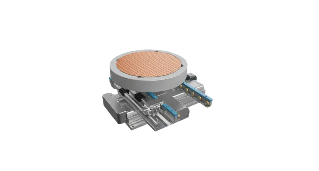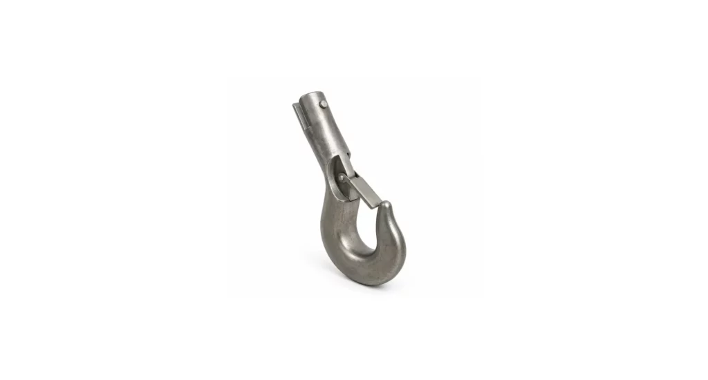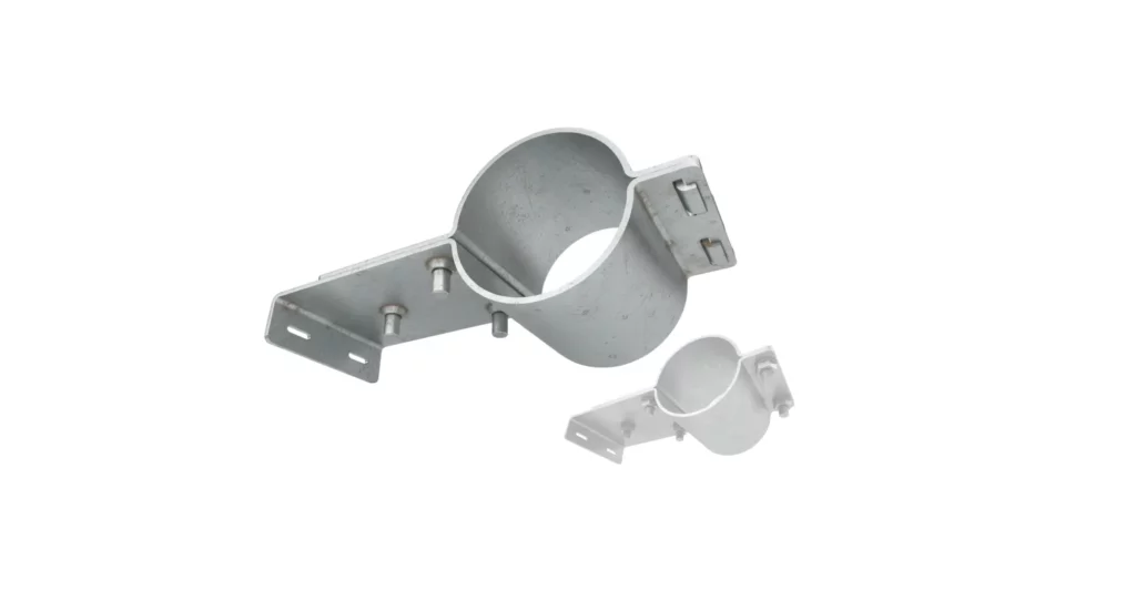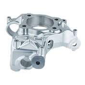
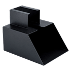
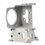
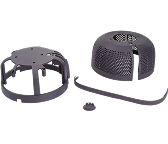
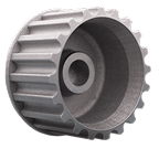
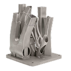
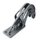
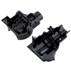
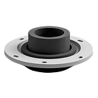

CNC precision machining is the computer-controlled subtractive manufacturing process used to produce components with tightly controlled dimensions – typically from ±0.002″ (0.05 mm) down to ±0.0005″ (0.013 mm) or better. It uses the same core tools and approaches as standard CNC machining (milling, turning, multi-axis machining), but applies far stricter controls: thermal management, high-resolution feedback, precision fixturing, calibrated tooling, and advanced inspection using coordinate measuring machines (CMMs).
The distinction is not the machine alone – it’s an entire system/approach: equipment capability, process control, operator expertise, and quality assurance. This guide explains how CNC precision machining works, what tolerances are realistic, and how to specify parts that achieve accuracy without unnecessary cost.

Key takeaways
- CNC precision machining achieves tolerances from ±0.005″ down to ±0.0005″ or potentially tighter for critical applications.
- Milling, turning, and multi-axis machining serve different geometry and tolerance requirements, so process selection is an engineering decision dictated by part geometry/form.
- Tightening tolerances from ±0.005″ to ±0.001″ can increase cost by 30 to 100% due to slower machining, more rigorous fixturing, and additional inspection.
- The most cost-effective precision parts specify tight tolerances only on functionally critical features.
What is CNC precision machining?
At its heart, CNC precision machining is no different from more basic CNC machining – the controlled removal of material using rotating cutters and G-code programmed toolpaths. What differentiates them is the degree of control over variation.
Typical tolerance tiers are:
- Standard CNC machining: ±0.005″ (0.13 mm)
- Precision machining: ±0.002″ to ±0.001″ (0.05–0.025 mm)
- Ultra-precision: ±0.0005″ (0.013 mm) or better
- Sub-micron processes (non-standard CNC): diamond turning, etc.
Precision vs Accuracy
- Accuracy defines how close a dimension is to the target.
- Precision defines how consistently that dimension is repeated.
A shop may hit ±0.001″ once (accuracy), but precision machining means holding that tolerance across and between batches, often measured using process capability (Cpk ≥ 1.33 to 1.67).
What enables precision
Precision CNC machining is achieved through aggressive control of all relevant error sources:
- Thermal expansion (machine + material)
- Tool deflection and wear
- Fixturing stability
- Machine calibration and backlash
- Measurement system resolution
You can think of precision machining as primarily an error management task, not just cutting capability.
How CNC Precision Machining works
CAD design and DFM
The process begins with a 3D CAD model defining geometry, and a 2D drawing specifying tolerances, and surface finishes. The most important step in this is carefully identifying critical vs non-critical features, to restrain the requirement for tighter tolerances to the must-have areas.
Early DDM collaboration with machinists is essential in optimizing this. Jiga enables this interaction before machining begins, reducing occurrence of redesign cycles and maintaining costs.
CAM programming and toolpath optimisation
CAM software converts geometry into toolpaths, either automatically, or more often with human-in-the-loop for higher spec components. For CNC precision machining:
- Stepovers and feed rates are reduced.
- Tool engagement (cut depth) is tightly controlled.
- Thermal load is managed with care.
- Finishing passes are optimised for minimal deflection and maximum precision.
Machine setup and fixturing
Setup often dominates the achievable precision of feature outcomes:
- High-stability fixtures minimise vibration.
- Datum referencing ensures repeatability.
- Multi-operation or setup parts require precise re-location.
Setup errors often exceed the intrinsic machine errors, potentially by an order of magnitude.
Execution and in-process verification
Machining proceeds, while making increased use of:
- Tool wear monitoring
- In-process probing
- Controlled coolant delivery
Precision parts often include semi-finish + rest + finish passes, to allow more complete stress relaxation and greater temperature stabilization.
Final inspection and quality control
Inspection is not simply a final step, it is part of the process loop:
- CMM measurement for critical features, potentially after each pass to confirm adherence to plan.
- Optical systems are used for micro-scale features too small to probe.
- Statistical sampling or 100% inspection is mainly a technical decision, driven by tolerance targets and project sensitivity.
In high-precision work, it is a surprising truth that inspection time can exceed machining time.
Core CNC Precision Machining processes
CNC milling
Rotating tools remove material from a generally fixed workpiece that moves on 4 orthogonal axes.
CNC milling is best suited to:
- Complex geometries
- Flat surfaces and pockets
- Multi-face components
- Complex and compound curvatures
Precision range: ±0.002″ to ±0.0005″, depending on setup and machine quality
CNC turning
The workpiece rotates, while fixed axially, while generally single-point tools traverse axially and radially to remove material.
This is suited to:
- Cylindrical parts
- Shafts, bores, threads
- Concentric features
The precision advantage that results from CNC Turning (and from good quality equipment) is excellent radial symmetry and concentricity control, and precisely repeatable axial positioning.

Multi-axis machining (5-axis+)
More advanced, multi axis machining centers can orient the workpiece AND cutter positions, for greater flexibility. Simultaneous movement across multiple axes enables complex geometries in fewer setups. These machines blur the difference between milling and lathe work, delivering highly coordinated and very complex motion/surfaces
The benefits that this delivers are:
- Reduced re-fixturing reducing errors
- Improved geometric accuracy with fewer tool changes and tool presentation compromises
The trade-off is higher programming complexity and machine cost, although these increases are commonly offset by improved machine time and reduced setup labor.
Tolerance standards in CNC precision machining
| Tolerance Level | Range | Equipment Required | Inspection Method | Cost Impact |
|---|---|---|---|---|
| Standard | ±0.005" | 3-axis CNC | Calipers | Baseline |
| Precision | ±0.002" | Tool monitoring CNC | Micrometers | +15–25% |
| Tight | ±0.001" | Thermal control, precision fixturing | CMM | +30–50% |
| Ultra | ±0.0005" | Climate-controlled machines | CMM, optical | +75–150%+ |
Cost vs tolerance reality
Below ±0.001″, cost increases non-linearly:
- Slower feeds and speeds
- Additional finishing passes
- More complex fixturing
- Increased inspection time

Materials used in CNC precision machining
Material choice pivotally affects achievable precision.
Metals
- Aluminium: Easy to machine but high thermal expansion (~23 µm/m·°C) which adversely affects high precision.
- Stainless steel: Stable but induces tool wear due to abrasive and work-hardening characteristics.
- Titanium: Strong but prone to deflection under high cutter pressure, and heat buildup due to poor thermal conductivity.
Plastics
- PEEK: High performance but sensitive to heat.
- Delrin (POM): Good dimensional stability.
- Nylon: Machines well, but many grades are moisture-sensitive, which can shift dimensions post-machining.
Thermal expansion example:
A 100 mm aluminium part with a 5°C temperature shift can move ~0.0115 mm (~0.00045″), which can overwhelm the entire tolerance at ultra-precision levels.
DFM for CNC precision machining
The most expensive precision parts are those where tight tolerances are applied universally, which is rarely necessary in the real world.
This is more likely to eventuate due to inexperience, so a basic DFM check should flag this early.
Identify critical vs non-critical tolerances
It is cost-critical to apply tight tolerances only where function requires, and the tightest tolerances only under extreme conditions
The use of more spline and standard tolerances, wherever possible, will pay dividends both in part cost and in production capacity.
Design for tool access and wall thickness
It is relatively easy to tune designed features to make higher tolerances more achievable, where required:
- Avoid deep, narrow cavities.
- Maintain adequate wall thickness to reduce deflection during cutting.
- Minimise long, poorly supported features.
- Pilot long holes with laser drilling.
- Step small diameter holes to shorten the at-risk sections where drill flexure can cause deviation.
Specify surface finish deliberately
Surface finish and tolerance are linked and require functional rather than optimistic or cosmetic specification:
- Bearing surfaces require both geometry and finish.
- Cosmetic finishes often do not justify tight tolerances, but imply the need for ultra precision cutting methods.
Get DFM feedback before committing
Engage suppliers early to:
- Validate tolerances
- Optimise setups
- Reduce machining steps
This process will often reduce the occurrence of extreme tolerance areas to those which are definitively needed, saving considerable machining effort/cost.
Tolerance stack-up and assembly reality
Precision matters most in assemblies, falling out of the component interactions that must be defined clearly, to deliver fit and function.
Worst-case stack-up
- 5 components at ±0.002″ implies a worst case of ±0.010″ total variation.
Over-tightening tolerance demands on every feature and every component is inefficient. Instead:
- Control critical interfaces and define them clearly at functional levels.
- Use statistical tolerancing where possible.
Process capability (Cp, Cpk)
Tolerancing as a standalone does not guarantee quality.
- Cp: process potential
- Cpk: process performance
Typical targets:
- Cpk ≥ 1.33 is generally acceptable
- Cpk ≥ 1.67 → critical applications
A supplier claiming ±0.001″ must demonstrate repeatability, not just one-off success.
Industries that rely on CNC precision machining
| Industry | Typical Components | Tolerances | Standards |
|---|---|---|---|
| Aerospace & Defence | Turbine parts, pump parts, flow control nozzles | ±0.001" or tighter | AS9100 |
| Medical | Implants, instruments | ±0.0005"–±0.002" | ISO 13485 |
| Automotive | Fuel systems, particularly injector pumps and nozzles, sensors | ±0.001"–±0.005" | IATF 16949 |
| Electronics | Connectors, heat sinks | ±0.001"–±0.003" | IPC |
These industries rely on CNC precision machining in applications where process controls, patient outcomes, or equipment durability failures are to be strongly avoided.
Finding the right CNC precision machining supplier
For precision work, suppliers are not interchangeable. Jobbing shops with standard equipment and maintenance practices will struggle with increased precision demands.
Evaluate suppliers on:
- CMM capability (bridge vs handheld)
- Environmental control (temperature stability)
- Calibration frequency
- Process documentation and traceability
- Maintenance and tool condition monitoring practices
- Demonstrated Cpk performance
Red flags
- “We can hold any tolerance”
- No inspection data provided
- Lack of process documentation or first article assessment reports
Jiga helps engineers compare suppliers based on real capability, not claims. With highly evaluated and precisely classified capabilities, you can be sure of getting to talk to the right type of service provider.
Prototype vs Production precision
Holding ±0.001″ on 5 parts is not the same as holding it on 5,000. Volume adapted suppliers operate in quite different modes from one off and prototyping shops.
Scaling challenges:
Stability over the longer term of high volume production requires rigor and thoroughness:
- Tools wear over time and must be monitored and evaluated regularly.
- Thermal drift is influential at the precision end of CNC operations and requires careful and ongoing strategic management.
- Fixture degradation is insidious and demands care from operators.
- Operator variation can be influential in delivering extreme precision.
Production precision is at least as much about process control as it is about machine capability.
Geometry complexity vs Precision
Some features are inherently harder to machine precisely:
- Deep bores, as tool centers wander and holes curve.
- Thin walls flex away from cutter forces and vibrate.
- Long slender shafts require local support at the cut – consider Swiss CNC machining.
- Internal corners rely on sharp tools and low deflection operations.
Designing around these constraints delivers opportunities to improve both cost and precision, often. with minor component changes.
Is CNC precision machining right for your part?
Use CNC precision machining on aspects of a part when:
- Critical features require ±0.002″ or tighter.
- Parts interface with bearings, seals, or press fits.
- Assembly alignment is critical.
Avoid it when:
- Features are cosmetic.
- Tolerances are found to exceed functional requirements.
- Large welded or fabricated structures are involved, as their intrinsic errors overwhelm machining precision.
Final insight
CNC precision machining is not about chasing the tightest tolerance – it is about controlling variation where it can adversely affect function.
Effective engineering does not specify precision everywhere, but applies it selectively, informed by function, assembly, and cost.