
Compression molding and injection molding are two of the most widely used processes for producing plastic, rubber, and composite parts. While they are often discussed together, they are fundamentally different in how material is shaped, what materials they support, and where their economic and technical benefits lie. For mechanical engineers and product designers, choosing the wrong process can result in wasted tooling cost, poor part performance, project delays, or production bottlenecks. This guide contrasts compression molding and injection molding across process fundamentals, materials, cost, cycle time, and applications – helping in the selection of the most appropriate method for each part, volume expectation, and budget.


Key takeaways
- Injection molding introduces pressurized molten polymer into a closed cavity under high pressure; compression molding places a measured charge into an open mold that closes the tooling to create the internal material-distribution pressure.
- Injection molding performs best with high-volume, complex, tight-tolerance thermoplastic parts; compression molding suits larger, thick-walled, simpler, and typically elastomeric parts.
- Injection molding primarily uses thermoplastics, while compression molding is commonly used for rigid thermosets, cross-linking rubbers, and composites.
- Injection molding has considerably higher tooling costs, but very short cycle times (typically seconds); compression molding uses simpler tooling but requires much longer cycles (minutes).
- The most appropriate process depends on part geometry, material requirements, production volume, cycle-time needs, and budget constraints.
- Component requirements exist in a complex matrix of properties which are only achievable through injection molding, or only through compression molding – and in a limited number of cases by either process, where the selection can be finely balanced.
What is injection molding?
Injection molding is a manufacturing process whereby net-shape, finished parts are formed from molten thermoplastic being injected under high pressure into a closed mold cavity. The material cools and solidifies inside the mold, forming a precise, repeatable reflection of the cavity in which it formed. Once solidified, the mold is opened and the finished component is pushed out (ejected).
This process is ideally suited to parts with complex geometry, thin walls, fine surface detail/finish, and tight tolerances – injection molding for medical devices is very widespread. As the process can be fully automated, and cycle times are short – often 10 to 60 seconds – it becomes increasingly cost-effective at scale. High upfront tooling costs and manufacture time are amortized via low per-part costs that result from high volumes.
The process supports a wide range of thermoplastics, including ABS, polypropylene, polycarbonate, nylon, thermoplastic elastomers, tough crystalline polymers like LCP, and performance enhancing fillers for demanding engineering applications. It is widely employed in consumer products, medical devices, automotive interiors, and electronics housings to list a small sample of applications for this universal process.
Injection molding produces critical components across medical and military sectors among many (all) others, including surgical instrument handles, syringe barrels, IV connectors, prosthetic housings, protective casings for electronic devices, precision weapon components, and ruggedized connectors – offering high-volume, repeatable manufacturing with tight tolerances and biocompatible or durable materials.
What is compression molding?
Compression molding is an alternate (typically thermoset molding) net-shape forming process for polymers. A pre-measured quantum of material – termed a charge – is deposited directly into an open, heated mold cavity. The mold then closes, applying pressure that causes the material to flow and fill the cavity. In the predominant case of thermoset molding compounds, heat and pressure serve to cure (or set) the material based on catalytic reactions, as crosslinking occurs.
Compression molding is commonly used with thermoset plastics, thermoset and, to a lesser extent, thermoplastic rubbers, silicone rubbers, and composite materials such as SMC (sheet molding compound) and BMC (bulk molding compound). These materials cannot be melted once cured, making them unsuitable for injection molding, other than in specialist cases.
The process is ideally suited to large, thick-walled, relatively simple parts. Compression molding tooling cost is typically low, tools are simple and considerably less costly than injection molds, but cycle times are longer, often several minutes, due to curing process speeds.
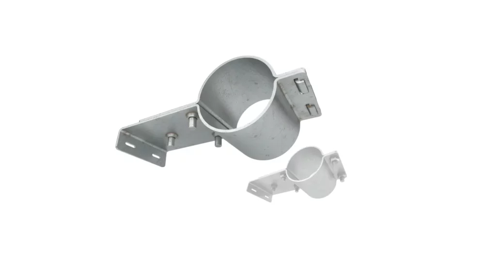
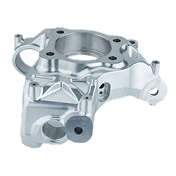
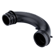
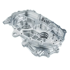
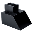
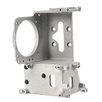
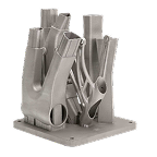
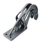
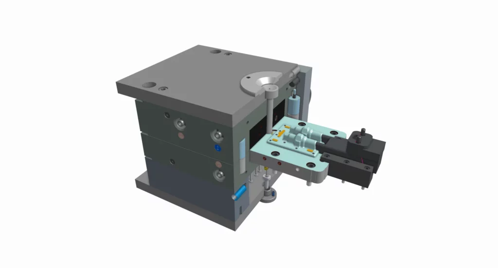
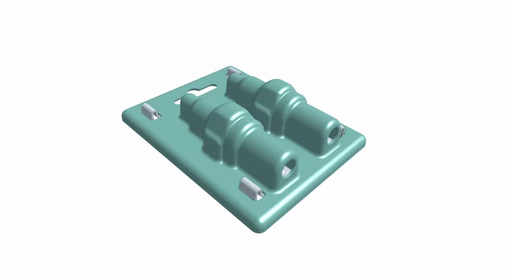
Compression molding in automotive and industrial sectors produces durable, high-strength parts such as bumpers, body panels, transmission bellows (as in Figs 1 and 2), electrical insulators, gaskets, seals, and composite structural elements, offering excellent dimensional stability, heat resistance, and vibration damping for high-volume, demanding applications. Similar niches are filled by compression molding, across most product sectors.
Although not core to this article, transfer molding is an alternate rubber molding process that is closely related to compression molding. It is primarily used for thermoset polymers, elastomers, and encapsulated electronic components. By this method, preheated material is placed into a transfer chamber that acts as a cylinder, into which a plunger is forced transferring the charge into the mold, where it cures. Unlike compression molding, the material flows into the cavity after the mold is closed, improving dimensional control and surface detail. Transfer molding is widely used for electrical connectors, semiconductor packaging, and components requiring precise inserts or encapsulation.
Injection-compression molding and rubber injection molding (RIM)
These both combine elements of traditional injection and compression processes, blurring the distinction between the two.
In injection-compression molding, material is injected into a partially open mold cavity, which then closes to compress the melt, improving surface finish, reducing residual stress, and enabling thin-wall molding. This hybrid approach lowers clamp force requirements while maintaining dimensional precision.
Rubber injection molding similarly injects preheated elastomer into a closed mold, where it fills the cavity and cures under pressure—functionally resembling compression molding but with automated, high-consistency material delivery. Both methods integrate controlled flow with compressive shaping for improved quality and efficiency.
The main difference: How material enters the mold
The central differentiator between compression molding and injection molding is the means by which material is introduced into the mold, and this divergence drives virtually all downstream tradeoffs.
In injection molding, molten material is forced through a nozzle, a runner system, and gate into a fully closed mold cavity, under high pressure. Flow behavior, gate design, and cooling dominate part quality.
In compression molding, the material is placed directly into the mold cavity prior to tool closure. As the mold progressively closes, the charge is distributed throughout the cavity and heat and pressure cure the part. There is no runner system, and flow distances are typically short.
This directly affects material choice, tooling complexity, cycle time, achievable detail, and waste.
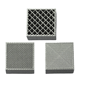
One approach to compression molding uses sheet molding compounds (SMCs)of various (often composite) materials. SMC compression molding clamps a flexible sheet molding material patch into a compression mold, and then uses heat and pressure to cure it to shape in the mold.
Key differences of compression molding and injection molding
Below is a high-level comparison of the two processes.
| Factor | Injection Molding | Compression Molding |
|---|---|---|
| Process | Molten material injected into closed mold | Charge placed in open mold, then compressed |
| Materials | Primarily thermoplastics | Primarily thermosets, rubber, composites |
| Part complexity | High detail, thin walls, tight tolerances | Simpler geometry, thicker walls |
| Tooling cost | Higher (complex, high-pressure molds) | Lower (simpler mold construction) |
| Cycle time | Fast (seconds per part) | Slower (minutes due to curing) |
| Production volume | High volume (100K–millions) | Low to medium volume |
| Waste | Low, controlled runners/sprues | Higher flash, trimming often required |
Advantages of injection molding
These elements seek to expand on the table above, in key areas:
Injection molding’s particular advantage is its ability to produce complex, high-precision parts at scale.
The process supports tight tolerances, thin walls, intricate features, and highly controllable surface finishes. Once tooling is validated, injection molding delivers high repeatability of parts with minimal inter and intra-batch variation, critical for reliable assemblies and consumer-facing products.
Cycle times are short – for small parts they can be of the order of a few seconds, enabling very high production rates and low per-part costs at volume. Automation further reduces labor cost and variability.
Injection molding offers a broad material palette, with thermoplastics available in filled, reinforced, flame-retardant, and medical- or food-grade variants.
For high-volume thermoplastic parts with challenging geometric or cosmetic requirements, injection molding is typically the only practical solution.
Disadvantages of injection molding
The primary barrier to selecting injection molding is its high upfront tooling and time costs. Steel molds are complex, precision-machined tools that can cost tens to hundreds of thousands of dollars and require weeks to months to produce.
Injection molding is also quite uneconomical for low-volume production or insecure and developing part designs. Each tooling revision can be costly, time-consuming and often tool-life degrading.
Part size (shot-weight) is constrained by machine capacity, and very thick sections are difficult to mold without shrinkage distortion or high residual internal stress.
Additionally, injection molding is largely limited to thermoplastics; thermoset and rubber materials are poorly suited to the high-shear, and incapable of the remelting nature of the process.
Advantages of compression molding
Compression molding offers distinct advantages for certain materials and part types.
Tooling is simpler and less expensive because the mold does not require high-pressure injection systems, runners, or gates. This makes compression molding attractive for lower-volume programs or parts with large footprints.
The process is ideal for thermoset plastics, rubber, silicone, and fiber-reinforced composites. These materials often exhibit excellent strength, thermal stability, and chemical resistance once cured.
Because the material is placed directly into the cavity, fiber length and orientation can be better preserved in composite parts, resulting in strong structural components. Thick, robust parts with consistent mechanical properties are a natural fit.
Disadvantages of compression molding
Compression molding’s limitations are quite severe and primarily they limit process speed and part precision.
Cycle times are significantly longer than injection molding due to the need for steep heating curves and the nature of the curing process, greatly limiting throughput. Flash is an intrinsic feature, due to the charge distribution proceeding as the tool closes. The resultant waste material typically requires secondary trimming operations, increasing labor cost and variability.
The process is unsuited to fine details, thin walls, and tight tolerances – high shear and high pressure filling are not possible. Complex features such as undercuts or intricate ribs are difficult or impossible to achieve without secondary operations. However, rubber molding can be stretched/peeled off tooling features as part of the demolding process.
Manual loading and unloading of material also increases reliance on skilled operators and reduces automation potential.
Materials suited to injection molding and/or compression molding
| Material | Injection Molding | Compression Molding | Typical Applications | Notes on Suitability |
|---|---|---|---|---|
| ABS | Housings, enclosures, consumer products | Thermoplastic; flows well under injection, not compatible with thermoset-style curing | ||
| Polypropylene (PP) | Rarely | Medical disposables, caps, hinges | Injection dominates due to thin-wall capability and cycle speed | |
| Polycarbonate (PC) | Transparent housings, medical components | Requires controlled injection molding due to melt behavior | ||
| Nylon (PA 6 / PA 66) | Gears, structural parts, connectors | Hygroscopic; injection molding provides best consistency | ||
| Glass-Filled Nylon | Structural housings, load-bearing parts | Fiber orientation controlled via injection flow | ||
| Acetal (POM) | Precision gears, valves, bearings | Injection molding preferred for dimensional accuracy | ||
| PEEK | Medical implants, aerospace parts | High-temperature thermoplastic; injection molding only | ||
| Polyethylene (HDPE / LDPE) | Rarely | Containers, medical trays | Injection used for thin and complex forms | |
| Thermoplastic Polyurethane (TPU) | Rarely | Flexible housings, seals | Injection preferred for repeatability | |
| Silicone Rubber (LSR / HCR) | Specialized | Medical seals, gaskets, flexible components | Compression or LSR injection used; conventional injection unsuitable | |
| EPDM Rubber | Gaskets, seals, automotive parts | Thermoset rubber; requires compression or transfer molding | ||
| Natural Rubber | Shock mounts, vibration isolators | Compression molding enables curing and thick sections | ||
| Phenolic Resin | Electrical insulators, heat-resistant parts | Thermoset; compression molding required | ||
| Epoxy Resin | Structural components, encapsulation | Compression molding for controlled curing | ||
| Polyester Thermoset | Panels, electrical components | Suited to compression molding | ||
| SMC (Sheet Molding Compound) | Automotive panels, enclosures | Compression molding enables fiber retention | ||
| BMC (Bulk Molding Compound) | Housings, electrical components | Flow optimized for compression molding | ||
| Fiber-Reinforced Rubber | High-strength seals, vibration damping | Compression preserves fiber integrity | ||
| Thermoplastic Elastomers (TPE) | Limited cases | Overmolds, soft-touch parts | Injection preferred for detail and thin walls |
Key engineering takeaways
- Injection molding is dominated by thermoplastics, materials that remelt, flow, and resolidify.
- Compression molding is dominated by thermosets, rubber, and composites, materials that cure irreversibly under heat and pressure.
- If your selected material cannot be re-melted, injection molding is almost never an option.
- If your part requires thin walls, tight tolerances, or fine detail, injection molding is usually. mandatory.
- If your part is thick, large, rubber-like, or fiber-reinforced, compression molding is often superior.
Cost comparison
Injection molding typically requires higher upfront investment. Tooling costs commonly range from US$5,000 to $100,000+, depending on complexity, cavitation, and materials. However, per-part costs drop dramatically at volume due to fast cycle times and automation.
Compression molding tooling is simpler and may range from $1,000 to $30,000+, depending on size. Per-part costs remain relatively flat with production volume, due to longer cycles and secondary trimming. As a result, compression molding is often more economical at low-to-medium volumes, while injection molding dominates at high volumes.
Break-even points depend heavily on part size and geometry, but injection molding often becomes competitive above ~50,000 to 100,000 parts.
Production speed and volume
Injection molding cycle times typically range from a few and up to 60 seconds, enabling millions of parts per year from a single mold. This makes it opyimum for mass production.
Compression molding cycles often range from 2 to 10 minutes, depending on material and bulk area thickness. Production volumes are therefore lower, and the process is better suited to low-to-medium volume runs.
Part design considerations
Design details and approaches will generally pre-define which process is appropriate, with a limited range of features and specification items in which selection is optional.
Design for injection molding
Injection-molding performs well with thin walls, uniform thickness, ribs, bosses, undercuts, cosmetic surfaces, and complex features. Designs for injection molding can integrate intricate and long undercuts using slides and lifters and hydraulic/electrical drives for side-actions. Tight tolerances and both smooth and precisely machined and chemically etched surface finishes are achievable, but tooling must be carefully engineered for operational reliability and long service life.
Design for compression molding
Compression-molded parts tend towards simpler geometries, thicker walls, and generous radii. Flash lines must be accounted for, and dimensional control is generally looser than for injection molding. Surface finishes tend towards functional rather than cosmetic.
Injection molding applications
Injection molding is used for medical components, consumer electronics housings, automotive interior parts, bottle caps and functional packaging, fasteners, and intricate mechanical components in which precision and volume are required.
Compression molding applications
Compression molding is commonly used for automotive panels, rubber gaskets and seals, electrical insulators, thick rubber mats, silicone rubber components, and composite structural parts such as larger enclosures and covers.
How to choose: Decision guide
Choose compression molding when:
- Parts are large, thick-walled, or heavy
- Materials are thermosets, composites, rubbers, or silicones
- Production volume is low to medium
- Tooling budget is limited
- Geometry is relatively simple
Choose injection molding when:
- Parts require tight tolerances and fine detail
- Material is thermoplastic
- Production volume is high (100K+ parts)
- Fast cycle times are essential
- Geometry includes thin walls and complex features
- Cosmetic requirements are high
Finding the right molding supplier
Suppliers typically specialize in one process. Key considerations include:
- Process expertise: Proven experience in injection or compression molding and recommendation from a trusted source.
- Material knowledge: Thermoplastic vs thermoset expertise is divergent and not interchangeable.
- DFM feedback: Strong suppliers identify design risks early and communicate clearly.
- Communication: Direct access to engineering teams matters.
- Scale-up capability: Ability to support prototype through production.
- Jiga stands out in a crowded space, as they act as introducer and concierge, rather than the more typical agent and proxy for invisible and indirect suppliers.
Jiga connects engineers, designers and buyers to vetted suppliers for both injection and compression molding, enabling direct technical communication and informed process selection.
Summary
Injection molding and compression molding serve different, complementary roles in manufacturing. Injection molding is best for high-volume, high-precision thermoplastic parts with complex geometry. Compression molding excels in larger, thicker, simpler parts made from thermosets, rubber, or composites at lower volumes. The process choice flows from material, geometry, volume, speed, and cost constraints.