
Tolerances define the accepted allowable variation from a part’s nominal dimensions, embodying design intent. No machining process produces perfectly identical parts, even on the same machine with the same program. The goal isn’t “perfect,” it’s functional interchangeability: parts assemble correctly, perform as intended, and can be inspected with clear pass/fail criteria. The influence in tolerancing is to ensure that the functional outcomes direct the part-extraction, such that clashes, friction, stress and interactions are all possible and optimized.
This guide explains practical CNC machining tolerances, how to impose realistic tolerance ranges, and how to communicate requirements clearly using drawing callouts and GD&T basics. We also cover how tighter tolerances drive cost, how secondary processes affect final dimensions, and how to work with suppliers to prevent expensive tolerance misunderstandings.
Understanding tolerancing methods is our purpose here – but sources of degraded tolerance must not be ignored.

Key takeaways
- CNC machining tolerances define allowable variation from nominal dimensions – often ±0.005″ (±0.13 mm) as a general or default limit, down to ±0.0005″ (±0.0127 mm) for highest-precision features.
- Tighter tolerances raise cost through slower machining, more inspection, more scrap risk, and sometimes specialized processes (grinding, honing, lapping).
- Geometric dimensioning and tolerancing (GD&T) (per ASME Y14.5 and ISO 1101) controls form, orientation, and location, not just size, so parts assemble and function consistently.
- Secondary processes (anodizing, plating, heat treat, passivation) can shift dimensions; specify whether tolerances apply before or after finishing.
- Material choice affects achievable tolerances; soft materials and plastics often move more and hold tight specs less predictably.
- Clear supplier communication is essential: the fastest way to blow a budget is a drawing that leaves tolerance intent open to interpretation.
What is CNC machining tolerance?
A tolerance is the permitted variation from a specified, nominal dimension. For example, a hole called out as 10.00 mm ±0.05 mm is acceptable anywhere from 9.95 mm to 10.05 mm. That window is the tolerance band. Where that hole is to receive a shaft, the tolerance band might move to 10.00 +0.1, -0.0. This ensures no interference is possible.
No process is perfectly repeatable – tool wear, temperature, machine stiffness, workholding, and material behavior all create variation. Tolerances acknowledge that reality, while ensuring the part still functions.
Why do tolerances matter for part function and fit?
Tolerances serve to ensure:
- Fit: shafts, bearings, fasteners, press-fits, slip-fits
- Function: sealing surfaces, alignment features, motion interfaces
- Interchangeability: parts can be swapped without hand fettling
- Inspection clarity: objective pass/fail criteria for QA

A useful rule is to understand that tolerances are inversely related to precision. Smaller numbers mean more precision, which typically results in higher part-cost.
Typical CNC machining tolerance ranges
Engineers often ask what tolerances can a CNC shop hold? The better question is perhaps what can be held reliably for this geometry, material, and inspection method? Still, having generic starting ranges helps you specify intelligently. A shop that makes automotive door hinges is not ideally placed to make gas turbine components.
Standard tolerances for general production
For non-critical dimensions, many shops default around ±0.005″ (±0.13 mm) unless otherwise specified (or use a general tolerance note like ISO 2768).
Precision tolerances for critical features
For mating features, bearing fits, and alignment pins, ±0.002″ (±0.05 mm) is common and achievable in many setups with appropriate process control.
High-precision tolerances for specialized applications
For critical bores, reamed holes, precision datums, and high-performance assemblies, ±0.0005″ (±0.0127 mm) may be achievable, but typically requires:
- stable setup + finishing strategy
- controlled temperature effects
- capable inspection (CMM, bore gages, air gages)
- sometimes post-process finishing (grinding/honing)
Practical tolerance range table (inch + metric)
Types of tolerances used in CNC machining
How you specify tolerances matters as much as the numbers – perhaps more. Different callout styles communicate different manufacturing intent and there is a great need for intentionality in this communication, as misunderstandings can have disruptive and expensive consequences.
Bilateral tolerances (±)
Bilateral tolerances allow variation in both directions from nominal.
- 25.00 ±0.10 mm >> acceptable: 24.90 to 25.10 mm
This is the most common method, for general features. Use for general dimensions where variation can go both ways without causing fit or function consequences.
Unilateral tolerances (One-sided)
Unilateral tolerances allow variation in one direction only.
- 10.00 +0.00 / −0.05 mm → acceptable: 9.95 to 10.00 mm
These serve as clearance-critical features which must be controlled relative to another part that must fit. If oversize is unacceptable in a shaft, an equivalent undersize rejection likely applies to a hole.
Limit tolerances (min/max)
Limit tolerances state explicit bounds without a nominal tolerance format.
- 9.95 – 10.00 mm
These are common in production drawings where an unambiguous min/max inspection criteria is necessary, simplifying the interpretation of measurement at inspection and often corresponding to go-no-go gauges.
General tolerances (ISO 2768)
A general tolerance note sets default tolerances for unspecified dimensions. ISO 2768 is commonly used (often paired with ISO 2768-1 for linear/angular and ISO 2768-2 for geometrical).
This approach serves in drawings with many non-critical dimensions where it is over-informing to tolerate every feature individually.
Geometric tolerancing (GD&T) using ASME Y14.5 / ISO 1101
GD&T basics provide a standardized language to control geometry – including:flatness, perpendicularity, position, profile, etc. – more effectively, enhancing basic plus/minus tolerances for a broader range of features.
Use this any time assembly depends on geometry, not just size – especially for hole patterns with corresponding part-fits, mating faces, and complex profiles.
GD&T fundamentals: Controlling geometry beyond size
GD&T exists because two parts can meet size tolerances and still fail functionally (through misaligned holes, warped sealing faces, off-angled co-axials, etc.). Geometric dimensioning and tolerancing controls the geometry that actually drives assembly and performance.
The FIVE categories of GD&T controls
- Form: straightness, flatness, circularity, cylindricity
- Profile: profile of a line, profile of a surface
- Orientation: parallelism, perpendicularity, angularity
- Location: position, concentricity, symmetry
- Runout: circular runout, total runout
Feature control frames: Reading GD&T callouts
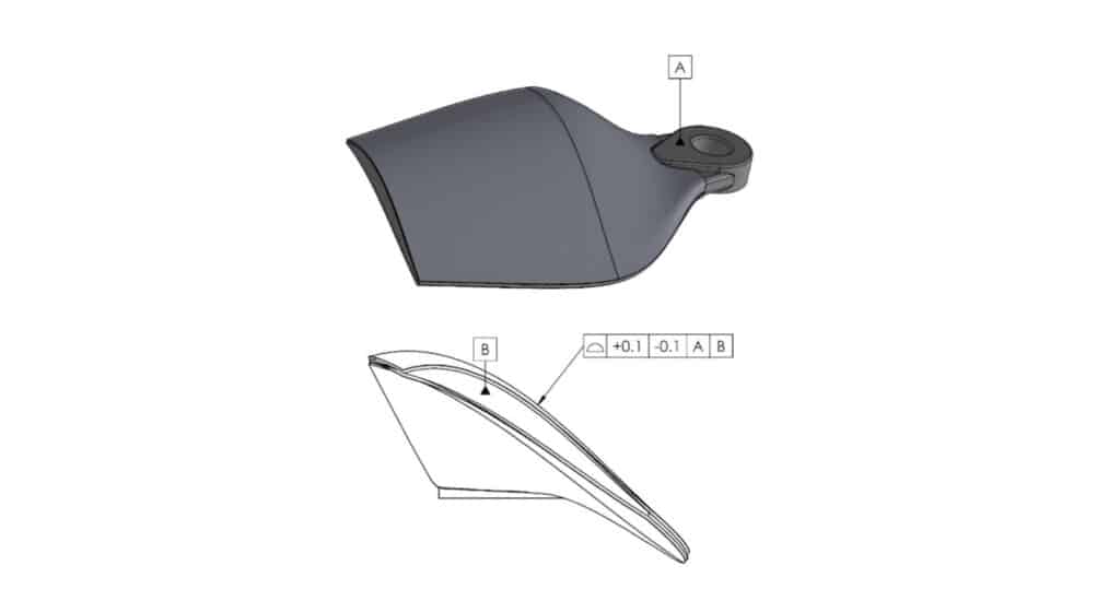
A feature control frame typically includes:
- GD&T symbol (e.g., position)
- Tolerance value (e.g., ⌀0.10)
- Modifiers (MMC/LMC/RFS
- Datum references (A | B | C)
This higher level of communication of intent/need tells manufacturing and inspection what geometry must be controlled, how tightly, and relative to what datums.
Datums and the datum reference frame
Datums define how a part is set up for machining and for manufacturing and inspection. Think of them as the functional reference surfaces/axes that establish:
- Primary constraint (A): usually a mounting face
- Secondary constraint (B): locates sideways
- Tertiary constraint (C): locks rotation
Effective datum selection mirrors how the part interfaces in the real assembly. It drives the creation of custom jigs for mass production and sets up the machine reference frame for toolpath creation and operational sequencing in machining.

When to use GD&T vs. Standard tolerancing
Use standard ± tolerances for:
- Non-critical sizes – features not involved in alignment or sealing.
- Simple manufacturing intent.
Use GD&T for:
- Hole patterns (position)
- Sealing/mounting faces (flatness, parallelism)
- Perpendicular relationships (perpendicularity)
- Complex contours (profile
- Rotating features (runout)
| GD&T Callout | Controls | Common Use Case | Why it’s useful |
|---|---|---|---|
| Position | Feature location | Hole patterns, dowels, fasteners | Improves assembly alignment vs ± tolerancing |
| Flatness | Surface form | Sealing/mounting faces | Prevents rocking/leaks |
| Perpendicularity | 90° relationship | Holes to faces, bosses | Prevents assembly bind |
| Profile (surface) | 3D contour | Cast-like shapes, sculpted surfaces | Controls shape without over-dimensioning |
| Runout / Total runout | Rotation quality | Shafts, bearing journals | Controls wobble and vibration |
What are the tolerances achievable with online CNC machining services?
Online CNC machining services and quoting platforms often advertise standard tolerances as default. commonly around ±0.005″ (±0.13 mm) unless specified otherwise.
Precision features in the ±0.001″ to ±0.002″ (±0.025–0.05 mm) range are frequently achievable when clearly called out and matched to a capable shop.
Some networks/suppliers support precision machining tolerances down to ±0.0005″ (±0.0127 mm) for specialized features, typically with additional review and inspection requirements. This can have a marked effect on part prices, so avoiding unnecessarily tight tolerances is a valuable habit.
Standard vs. Precision service tiers
In practice, tolerancing operates in tiers:
- Standard service: general machining, basic inspection
- Precision service: tighter features, more controlled finishing, expanded inspection
- High-precision service: specialized machines, processes, controlled measurement
How supplier networks affect achievable tolerances
Online outcomes depend heavily on:
- Whether the platform routes tight-tolerance jobs to the right shops. This is considerably more likely with the larger supplier networks connected through Jiga.
- Inspection capability (CMM, calibrated gauges)
- Materials availability and traceability
- Whether machinists actually review drawings, not only 3D models. While models are informative, they provide no clarity about functional limitations that tolerances directly control. A model based quote is an incomplete quote.
Communicating tolerance requirements when ordering online
This is where many CNC projects go awry – the CAD model looks fine, but the drawing tolerance intent is unclear, or simply isn’t reviewed with a full understanding of the design intent.
Black-box platform limitations
A common concern with purely automated platforms is loss in translation:
- Quoting may prioritize gross-geometry and material over finesse and precise fit issues
- Drawing tolerance callouts may not get skilled human review
- Automated DFM warnings often create noise, by flagging issues that a skilled machinist knows are of no difficulty
Automated vs. Human DFM
Automated DFM can be useful for gross issues, but complex assemblies require skilled and experienced human judgment:
- Which datums are functional?
- Which tolerances are critical vs desirable or over-specified?
- Is there a simpler spec that preserves function?
Capability-based matching
Not all shops can execute:
- Tight position tolerances on hole patterns
- Runout callouts for rotating features
- Consistent bore size on deep holes
- Precision surface finishes
Capability matching is the difference between quoted and delivered components. This can be influenced by equipment, personnel skill level and throughput-pressure in lower grade suppliers.
Honest quoting behavior
The best online CNC machining services will connect you with suppliers that:
- Flag unrealistic tolerances early.
- Propose alternatives (GD&T, datum changes, process changes)
- Decline work they can’t do well rather than gamble and risk shipping out-of-spec parts.
Preventing costly mistakes
Tolerance miscommunication causes:
- Rework and schedule slips
- Parts rejected at incoming QC
- Assembly failures discovered too late
Jiga’s approach emphasizes direct supplier communication and capability-based routing – imperative when tolerances and GD&T requirements are nuanced.
Factors that influence achievable tolerances
Use this as a reality-check checklist before tightening specs:
Part function and mating features
Tight tolerances should be concentrated where parts mate, seal, align, or move.
Material behavior and machinability
- Softer metals and plastics can burr and smear
- Plastics can creep, warp, and move with temperature and distort under machining loads
- Hard alloys increase tool wear and heat input
Process capability: Milling vs. Turning vs. Grinding
- Turning often excels at roundness/concentricity on rotational features
- Milling excels at prismatic geometry and patterns
- Grinding/honing excels for ultra-tight size and finish
Tool wear and deflection
Long tools, thin walls, deep pockets, and tough materials increase deflection and drift.
Thermal stability and environmental control
Temperature changes affect both machine and part. Tight-tolerance work often benefits from controlled environments and stable process timing.
Secondary processes and their dimensional impact
Finishes can add thickness or cause movement:
- Anodize thickness buildup
- Plating buildup
- Heat treat distortion
- Coating thickness variability
Cost and lead-time impacts of tighter tolerances
Tighter tolerances aren’t intrinsically bad, they’re just expensive when overused or misapplied.
Why tighter tolerances cost more
Common cost drivers:
- Slower feeds/speeds and extra finishing passes for tighter dimensional control
- Toolpath refinement such as spring passes, boring/reaming sequences
- More setups and more complex workholding
- Higher scrap risk at final inspection
Inspection requirements and CMM measurement
Tighter specs often require:
- Reference calibrated and higher skill level inspection equipment
- More tightly controlled measurement procedures
- More inspection/effort/time per part
Scrap risk and quality thresholds
If the applied tolerance band is extremely tight, normal process variation can create rejects even when the shop is doing great work. This increases cost, extends lead time, and may drive expensive process changes.
Every tolerance has a process capability cost. If the feature doesn’t need it for function, there’s no benefit in paying for it.
Best practices for specifying tolerances on drawings
Use tight tolerances only where function requires
At the outset, it’s critical to identify the functional features:
- Interfaces
- Hole patterns
- Sealing faces
- Bearings and shafts
Apply necessary and functional tolerances to these, and relax everything else.
Specify GD&T for geometric requirements
Use GD&T when geometry drives assembly. It often allows more manufacturing freedom while improving functional control. When parts are a precise mating-fit, they tend towards self-jigging, reducing assembly process complexity and error potential.
Ensure clarity for production and inspection
- Define datums clearly
- Avoid conflicting callouts
- Make inspection intent obvious
- Specify critical-to-function features explicitly
Account for secondary operations in tolerance stack-up
If anodizing/plating/heat treat affects final size:
- specify “pre-finish” dimensions, or
- note “dimensions apply after finishing,” and align with the supplier’s process plan
Summary
Tolerances are the language of functional intent in CNC machining.
- Overly loose tolerances risk poor fit and function
- Overly tight tolerances inflate cost and lead time
The best approach is targeted precision: apply tight tolerances only where they are critical, use GD&T to control geometry for assembly, and account for material behavior and secondary processes. Clear communication, especially when ordering online, prevents expensive mistakes and rework. Jiga supports this by matching projects to vetted manufacturers capable of meeting tight tolerance requirements and enabling direct supplier collaboration for nuanced drawings and GD&T needs.