Home / Resource Center / Press Fit Tolerances: A comprehensive guide to design, calculations, and applications

Press Fit Tolerances: A comprehensive guide to design, calculations, and applications

Jiga helps you source high-quality, cost-competitive custom parts faster by partnering directly with vetted manufacturers.

Jiga has been an unbeatable combination of speed, quality, and price! I really like the streamlined communication platform directly with vendors, and I appreciate the prompt attention of our account manager! I have sourced a variety of custom metal parts so far and it’s been a flawless experience.

A man in an astronaut suit holding an american flag.
Jerry S.
Mechanical Engineer

Table of Contents

Whitepaper

The complete guide to
Design for Manufacturing and Assembly

dfm whitepaper preview

Tips to simplify designs

Practical steps to early DFM integration

Strategies to choosing suppliers

Actionable advice from industry leaders

Whitepaper

The complete guide to
Design for Manufacturing and Assembly

dfm whitepaper preview

Tips to simplify designs

Practical steps to early DFM integration

Strategies to choosing suppliers

Actionable advice from industry leaders

press fit tolerances

Press fitting (also called interference fitting) is perhaps the most ancient form of metal joining, relying on elastic and plastic part deformation to couple an inserted part to a receiving part. 

It is, in many ways, the metalworking equivalent of NAILING parts together! A Bronze Age swordsmith would very clearly understand the up-to-date approach to press fitting and the precision issues that it implies.

It’s a common and highly current mechanical assembly technique where two parts are joined by forcing one into the other, typically with a cylindrical interface, with precise dimensional tolerances – in modern processes.

The use of press fits predates all modern technologies, but the understanding of the fundamental behavior and the ability to manufacture parts with very high precision and tight tolerances has enabled the refined use of the approach to become a cornerstone in most mechanical assemblies and moving (and non-moving) part interactions.

The ability to selectively create tightly controlled interferences from the tightly fixed to the smoothly running creates options in friction and radial stress, ensuring a secure, permanent connection without fasteners or adhesives.

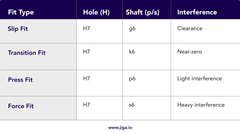
Two analysis methods are used in defining the fit of a shaft and a hole. These are termed ‘shaft basis’ and ‘hole basis’. As holes are simpler to manufacture with precision, the shaft-basis approach is more typical. Shaft-basis is typical when the shaft is a pre-existing and fully defined component – for example, when parts are to be made to fit a purchased precision bar/rod. Adjustment of a shaft to fit a pre-existing hole is how hole-basis operates.

The process and interference implications are identical. The difference lies entirely in which part is adjusted to define the fit. 

This guide details the fundamentals, tolerances, engineering calculations, material options, surface finishes and common applications/troubleshooting of press fits. It is presented from the more common, hole-basis perspective.

What is a Press Fit?

A press fit relies on controlled interference between a shaft (male part) and a hole (female part). The shaft is slightly larger than the hole, requiring force for assembly. Once joined, friction holds the parts together.

It is appropriate to offer definitions of the terminology used, so that understanding can be clear: 

  • The interference in a fit is the difference between shaft and hole diameters (e.g., +0.05mm). This defines the degree of ‘overlap’ of the shaft/hole diameters that provides the resistance to fit and the binding forces between the two parts.

  • The tolerance applicable in the feature diameters is the allowable deviation from nominal dimensions (e.g., H7/p6).

  • The retention force covers two factors – the axial and rotational forces required to overcome the interference and either disassemble the fitted parts or cause relative motion in axial or rotational directions.

Types of Press Fits

Press fits are categorized by the interference level that binds the two parts together, resulting from the overlap of radial dimensions:

Table comparing light, medium, and heavy press fits by interference range, typical application, and example use in mechanical assemblies.

Press Fit Tolerance classes

Standardized under ISO 286, press fits use hole-basis systems (e.g., H7/p6):

  • Hole Tolerance (H7): Always has a positive allowance (e.g., ⌀10.000–10.018mm). This implies that the hole diameter cannot be less than 10mm

  • Shaft Tolerance (p6): Ensures interference (e.g., ⌀10.022–10.035mm).

Common ISO Tolerance Grades

Table listing fit types (Slip, Transition, Press, Force) with corresponding hole, shaft parameters (H7, g6/s6), and interference types (clearance to heavy interference).

Where the press fit is defined on a hole basis, the variances in diameter (and therefore clearance/tightness of fit) are defined in shaft diametral variations.

Diagram showing three types of fits—press fit, transition fit, and sliding fit—between a shaft and hole, each illustrated and labeled with brief descriptions highlighting press fit tolerances.
The three types of engagement in press fitted parts (on a hole basis)

Engineering Calculations

Table displaying shear pin specifications, including nominal size, pin diameter, crown height, preferred lengths, single shear load, and suggested press fit hole diameter with relevant press fit tolerances.

Interference Calculation

Interference = D(shaft) – D(hole)

This example illustrates one possible fit tolerance:

  • Hole: ⌀10.000 – 10.018mm (H7)


  • Shaft: ⌀10.022 – 10.035mm (p6)


  • Min. Interference: 10.022 – 10.018 = 0.004mm


  • Max. Interference: 10.035 – 10.000 = 0.035mm

Assembly or Press Fit Force (F)

F = μ ✕ P ✕ π ✕ D ✕ L

Where:

  • μ = Coefficient of friction (0.1–0.2 for steel)

  • P = Contact pressure (from Lamé’s equations)

  • D = Nominal diameter

  • L = Engagement length
A graph showing force versus press fit penetration, with labeled points for start of contact, insertion commences, press fit depth, and bottoming out.
This plot shows the sequence of forces required to complete a press fit. At first contact there is force but no engagement, the insertion force sees a peak as the engagement commences, with a drop off and then rising forces until engagement is completed. The final, near vertical force section shows what happens in a bottoming-out insertion, where the shaft sits onto a shoulder or blind bottom in the hole, showing increasing resistance to insertion with no movement.

Contact Pressure (P)

Contact pressure is highly dependent on the wall thickness surrounding the hole. Elasticity in a thin-walled receptacle or local weak areas in this will alter the results considerably and render calculations moot. It is typically best to run a trial and approximation, where the hoop stress can be accommodated in these elastic ways. For a solid shaft in a thick-walled hub:

P = E ✕ δD ✕ (1−ν)(1+ν)

Where:

  • E = Young’s modulus of the material(s) (e.g., 210 GPa for steel) 
 
  • δ = Radial interference 
 
  • ν = Poisson’s ratio of the material(s) (~0.3 for metals)
Diagram of a shaft inserted into a hole, showing the shaft being compressed inward and the hole being stretched outward by the fit.
This section with exaggerated interference illustrates the stretching forces applied to the hole, compression applied to the shaft and the resulting hoop stress.
A metal shaft with a chamfered edge is aligned with a cylindrical hole; text notes the chamfer helps guide the shaft smoothly, reduces damage, and aids in meeting press fit tolerances.
To reduce engagement issues and the risk of skew fit and part bruising, a gentle lead in allows a more progressive engagement that self-centers more effectively. A 30° chamfer on the hole will encourage centering without any loss of fit precision.

Material & Surface Finish Considerations

Material Selection

  • Steel-on-steel: Most common (high strength, predictable expansion).


  • Aluminum: Lower interference forces (softer material).


  • Steel-on-phosphor-bronze: Typical of self lubricating bearing bushes, inserted into steel receptacles.


  • Plastic-on-plastic or plastic-on-metal: Risk of creep—use light press fits to avoid relaxation and fracture.

Surface Finish

The optimal roughness (Ra measure): 0.8–3.2 µm for metals.

  • Metal surfaces that are too smooth (<0.4 µm) experience a higher degree of micro-welding, creating a risk of galling and contact pressure loss as material is micro-damaged.


  • Surfaces that are too rough (>6.3 µm) typically experience weakened retention force as peak contacts are smeared, reducing the planned interference.
Sean B.
trustpilot Jiga
Mechanical Engineer
"I've recommended it to all my colleagues in manufacturing."
In an industry where competitors often act as mere middlemen, Jiga truly stands out by empowering buyers. Their platform enhances communication with suppliers, streamlining the entire process. The easy payment system simplifies interactions with overseas vendors, eliminating the hassle of dealing with international transactions. I’ve found such value in Jiga that I’ve recommended it to all my colleagues in manufacturing.
Jiga is the best way to get the parts you need, when you need them.

Applications

A table lists industries, use cases, and their related interference types for Automotive, Aerospace, Electronics, Medical, and Tooling sectors.

Troubleshooting Press Fits

Table listing common fitting issues, their causes, and solutions, including loose fit, cracked hub, difficult assembly, and fretting corrosion.
Diagram showing a cylinder with a hole, illustrating hoop stress on the hole wall and a crack along the cylinder due to tensile failure—press fit tolerances may influence stress distribution and potential crack initiation.
The most extreme failure mode in a press fit is one in which the hoop stress on the hole component exceeds the ultimate tensile strength of the material, and a fracture occurs.

Advanced Techniques

  • Thermal or Cryogenic Assembly: Heat hub/cool shaft for easier insertion (e.g., bearings). This can induce high retention forces while allowing lower assembly forces, reducing the risk of part damage.


  • Hydraulic Pressing: Controlled force application (avoids over-exhertion/impact damage and assists in fully asserted linearisation without initial skew-fit and bruising).


  • Finite Element Analysis (FEA): Simulates stress distribution.

Conclusion

Press fits offer a simple yet powerful solution for joining components without the need for adhesives, fasteners, or welding. By relying on controlled interference between mating parts, press fits create durable, high-strength connections that are widely used in mechanical assemblies, from automotive drivetrains to consumer electronics. 

The effectiveness of a press fit hinges on careful design considerations—such as material compatibility, tolerance control, and surface finish—which directly impact performance and reliability.

As manufacturing methods become more precise and materials science continues to evolve, press-fit technology remains a staple in both traditional and modern applications. The ability to provide clean, compact, cost-effective, and above all permanent but disassembly-capable joints makes it especially appealing for automated assembly and miniaturized devices.

With growing demand for sustainable manufacturing and disassembly for recycling, the reversible nature of many press-fit based designs also aligns with circular economy goals. Press fit as a technique its worth as both a timeless and forward-thinking engineering solution.

Picture of Jon
Jon
Jon is a dynamic and accomplished professional with a rich and diverse background. He is an engineer, scientist, team leader, and writer with expertise in several fields. His educational background includes degrees in Mechanical Engineering and Smart Materials. With a career spanning over 30 years, Jon has worked in various sectors such as robotics, audio technology, marine instruments, machine tools, advanced sensors, and medical devices. His professional journey also includes experiences in oil and gas exploration and a stint as a high school teacher. Jon is actively involved in the growth of technology businesses and currently leads a family investment office. In addition to his business pursuits, he is a writer who shares his knowledge on engineering topics. Balancing his professional achievements, Jon is also a dedicated father to a young child. His story is a remarkable blend of passion, versatility, and a constant pursuit of new challenges.

Actionable bits of content on procurement and supply chains, straight to your inbox

Jiga is free to use instantly. Pay only for parts you source.