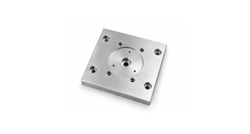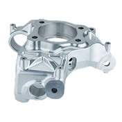
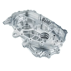
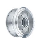

3-axis CNC machining is a subtractive manufacturing process in which rotating cutting tools traverse along three linear axes – X (left-right), Y (front-back), and Z (up-down) – removing material from a stationary workpiece. This typically involves the workpiece moving, clamped to the machine table, in X and Y and either the table or the cutter moving in Z.
It is the most widely available CNC machining method globally, and the lowest cost equipment in its class. This delivers the most cost-effective solution for parts with simple to moderately complex, low curvature geometries, without complex internal features and typically requiring the bulk of machining from only one, or perhaps two directions.
For most engineering projects requiring machined parts, 3-axis CNC machining is the logical starting point of process selection. Where part geometry requires little or no cutter access from multiple angles or includes undercuts and complex surfaces, 3-axis machining is the go-to choice. It provides the best balance of cost, speed, and precision.
However, simplicity is also the primary constraint: success depends heavily on part orientation, setup strategy, surfacing simplicity, and feature accessibility.
Key takeaways
- 3-axis CNC machining is the most heavily utilized and cost-effective CNC process for prismatic and only moderately complex parts.
- Typical tolerances range from ±0.005″ (general) to ±0.001″ (precision), depending on setup strategy and material.
- The primary limitation is tool access – features must be reachable from above, otherwise they’ll require multiple setups which degrade precision and process speed.
- Most machining challenges arise not from the machine, but from geometry, fixturing, and setup decisions.

What is 3-Axis CNC machining?
3-axis CNC machining is the most widespread computer-controlled manufacturing process, in which a hardened and typically multi-faced cutting tool removes material from a fixtured workpiece by moving the workpiece, or cutter, or both, along the three orthogonal axes described above.
The tool always approaches the part perpendicular to the machine bed, which considerably simplifies programming and fixturing, compared with multi axis centers, but greatly restricts access to more complex features and geometries.
This constraint embodies both the strength and the limitation of 3-axis machining. The approach excels at producing essentially flat, prismatic, and 2.5D geometries requiring high precision and repeatability.
However, features located on multiple faces or requiring angled access often necessitate reorientation, or alternative and precision-reducing machining strategies.
In practice, 3-axis CNC machining is not just a machine capability – it is first a design constraint. Engineers who understand this constraint can design parts that are faster, cheaper, and more reliable to produce – but the design-compromises that this necessitates can overwhelm design intent, necessitating more complex strategies be adopted.
How 3-Axis CNC machining works
The process begins with a virtual design executed in CAD (computer aided design). This model is interpreted through CAM (computer aided manufacturing) software, integrating non-CAD instructions in a 2D drawing such as material, tolerances, finishes etc. While automated machine instructions from the CAM software can be used, it is common for operators to interpret the process through a skilled interpretation that goes beyond basic CAM analysis.
A skilled machine operator progresses through G-code programming, setup optimization, tooling and coolant selection, simulation/dry running, machining, and inspection.
The CAD model is converted into toolpaths by the CAM software, which defines how the cutting tool will present to the work, to remove material. These toolpaths are written in machine-readable form using position, feed-speed, spindle-speed and too-offset instructions, in G-code,
Setup is the skilled aspect in which much of the process complexity resides. The workpiece must be securely fixed against well defined and reliable datums, often using a basic machine vice, T-slot clamps, or custom fixtures where necessary. Orientation decisions at the programming stage determine which features can be machined in a single setup, and which will require reorientation.
When sourcing 3-axis CNC machined components through Jiga, engineers are enabled to communicate directly with the assigned machinist, to review toolpath strategies, cutter selection, fixture orientation, and feature accessibility prior to production start. This reduces iteration and can assist in moderating costs and improving quality, when machine operator DFM feedback is integrated into design iterations.
From CAD model to G-code
The digital model defines geometry, but manufacturability depends on how toolpaths are generated. Despite the digital nature of the process, the interpretation of part geometry and optimization of processes are highly skilled, human operations.
Machine setup and fixturing
The billet of raw material is positioned and clamped – this step often determines final accuracy more than the machine itself. Positional errors relative to machine datum faces, insufficient retention, or inappropriate clamping point selection can allow absolute error, movement that creates progressively increasing error, or vibration that degrades local precision and surface finish.
Cutting operations and tool changes
Material is removed through multiple roughing and finishing passes of progressively reduced cut-depth and feed speed, with tool changes to accommodate the range of features to be cut. Coolant of a material-appropriate type is generally used, to improve cut characteristics, reduce heat and associated dimensional changes, and maintain cutter sharpness/life.
Inspection and finishing
Parts are measured and finished to meet dimensional and surface requirements. The first part from a new setup/programming requires intensive evaluation to ensure it conforms to expectations. Subsequent parts SHOULD achieve the same level of precision and quality, requiring diminishing inspection – although process maintenance routines are necessary to ensure this.
Capabilities of 3-Axis CNC machining
Geometric versatility
3-axis CNC machining handles flat surfaces, pockets, slots, and simple contours efficiently. More complex features such as undercuts are feasible, using T-slot and dovetail cutters. Limited angled faces can be cut using appropriately tapered tooling, and some complex profiling is possible, using custom pillar cutters.
Precision and tolerances
With well planned and effective setup, appropriate toolpath planning and cutters on good condition, tolerances of ±0.001″ are achievable where required, though more relaxed tolerances help to reduce costs.
Material compatibility
3-axis machining supports all but the hardest metals, engineering plastics, machinable ceramics, some natural materials, and composites – operating across a wide range of applications and machine parameters.
Production speed and automation
High material removal rates and automation enable efficient production for repeatable parts. Robotic loading and unloading, integrated/automated quality control, and regular tool condition and offset checks allow lights-out operation, where volumes and costs require it.
Limitations of 3-Axis CNC machining
Restricted geometry access
The tool is presented to the workpiece from a single direction (per setup), limiting access to cut more complex features.

Multiple setups and alignment error
Parts requiring machining on multiple faces must be unclamped, repositioned and reclamped, introducing alignment and positional risks that limit part or feature precision.

Tool deflection and depth limits
A straightforward relationship exists between feature width, cut depth, tool diameter, and processing speed. Deep cavities and slender tools increase the risk of tool or material deflection, resulting in local dimensional errors and surface finish issues due to vibration (chatter).
Where 3-Axis CNC machining projects break down
Most trouble issues in execution of 3-axis machinings originate from design and setup decisions, not machine capability, which is typically addressed fully before or during the CAM stage.
Common failure modes include:
- Multi-setup misalignment, causing positional errors between features
- Poor datum strategy, leading to cumulative errors and tolerance drift
- Deep pocket machining, with resulting chatter and poor surface finish
- Thin-wall features combined with more aggressive cut depths, causing feature deformation during cutting
- Inappropriate main-machining orientation rendering features inaccessible without excessive setups
3-axis CNC machining must be treated as a system of constraints to be accommodated, not an open series of essentially unrelated cutting stages.
Setup strategy: The hidden complexity of 3-axis machining
3-axis machining commonly demands multiple setups to overcome cutter presentation issues, making setup strategy critical.
Key considerations:
- Datum transfer: maintaining consistent reference points across setups can be challenging and requires careful addressing of datum compliance
- Fixture repeatability: ensuring identical positioning each cycle is the largest factor in datum transfer
- Reorientation planning: minimizing the number of setups
- Workholding method: vices, soft jaws, or vacuum fixtures – custom tooling for part location and locking can add considerable cost
In many cases, setup quality and reliability has a greater impact on precision than does machine and cutter quality/condition.
Tolerance stack-up and alignment risk
Tolerance is primarily not about machine capability, once a basic standard of equipment is achieved – it is about how error accumulates, particularly in more extended cutting strategies.
In multi-setup machining:
- Each setup introduces positional variation
- Errors compound across features
- Misalignment between faces becomes the dominant issue
Designing with clear datums and minimizing reorientation reduces risk significantly.
Is your part suitable for 3-axis CNC machining?
A practical assessment framework answers these questions, to enable smart process selection:
- Can all features be accessed from one, or two directions?
- Do required setup changes interfere with delivering high tolerance features?
- Are undercuts, angled features, or 3D curvatures required?
- Does the part require machining on more than two faces?
- Are feature depths achievable, relative to tool diameter?
If constraints are violated, multi-axis machining will be required – though smart toolpath strategies, cutter selection, and moderate DFM changes can often enable marginal cases.


What drives cost in 3-axis CNC machining?
Cost is driven by a combination of setup, machining time, and complexity.
Primary drivers:
- Number of setups, being typically the largest cost factor.
- Material volume to be removed
- Tool changes and tool wear
- Tolerance requirements
- Surface finish requirements
Design decisions directly and heavily influence cost. Reducing setups generally has a greater cost impact than reducing machining time, as they require high value labor intervention.
Applications of 3-Axis CNC machining
| Sector | Typical Components | Why 3-Axis CNC is Suitable |
|---|---|---|
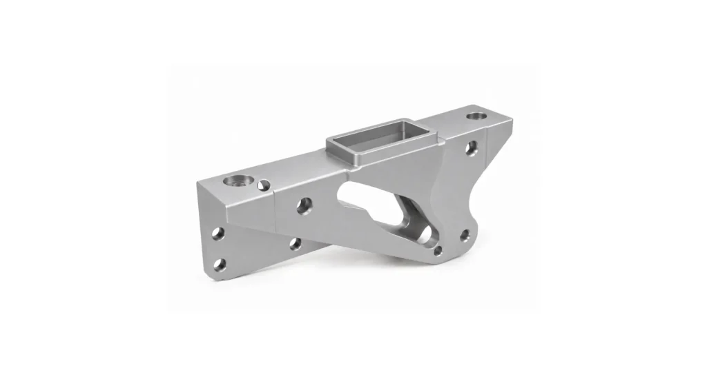
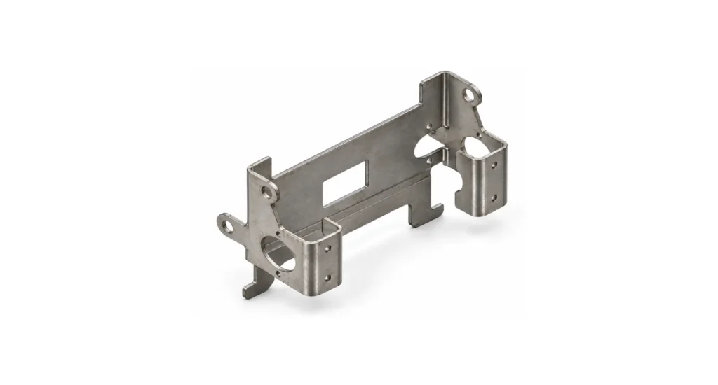
| Aerospace & Automotive | Structural brackets, mounting plates, housings, covers | Prismatic geometries, tight tolerances, repeatable hole patterns, flat datum control |
| Medical Devices | Instrument handles, device enclosures, trays, surgical guides | Clean geometries, good surface finish, biocompatible materials (e.g. aluminum, PEEK) |
| Electronics & Consumer Goods | Heat sinks, housings, fixtures, faceplates | Efficient pocketing, fin structures, cosmetic surfacing, high repeatability |
| Industrial Equipment | Machine guards, base plates, actuator mounts, sensor brackets | Robust parts with planar features, threaded holes, and standard tolerances |
| Robotics & Automation | End-effector plates, gripper components, mounting interfaces | Accurate interface geometry, rapid iteration for custom automation tooling |
| Energy (Oil, Gas, Renewables) | Valve blocks, manifolds (simple), mounting frames, enclosures | Suitable for block-like parts with drilled passages and milled faces |
| Mold, Die & Tooling | Electrodes, simple cavities, jig plates, fixture bases | Effective for 2.5D geometries, flat cavities, and support tooling |
| Prototyping & Low-Volume Production | First articles, functional prototypes, bridge production parts | Fast setup, low programming complexity, cost-effective for iteration |
| Defense & Military | Mounting hardware, equipment housings, ruggedized enclosures | Repeatability and durability for standardized, non-organic geometries |
| Marine | Brackets, housings, deck hardware components, propulsion elements | Corrosion-resistant materials with relatively simple machined features |
| Food & Beverage Equipment | Frames, guides, hygienic housings, tooling plates | Smooth finishes, cleanable geometries, stainless steel compatibility |
| Packaging Machinery | Guide rails, cutter mounts, forming plates | High repeatability, wear-resistant materials, simple multi-face machining |
| Semiconductor Equipment | Vacuum plates, alignment fixtures, component mounts | Precision flatness, hole location accuracy, controlled surface finish |
| Construction & Heavy Equipment | Mounting brackets, wear plates, adapter plates | Thick-section parts, robust machining, low complexity geometries |
| Furniture & Architectural Hardware | Brackets, connectors, decorative plates | Flat profiles, drilled features, cosmetic finishing options |
Materials used in 3-Axis CNC machining
Material selection heavily influences machining behavior, processing times and quality of outcomes.
| Material Family (Examples) | Benefits in 3-Axis CNC Machining | Issues/Limitations |
|---|---|---|
| Aluminum Alloys (6061, 7075) | Excellent machinability, high material removal rates, good surface finish, low tool wear | Lower stiffness than steels, burr formation, thermal expansion can affect tight tolerances |
| Carbon Steels (1018, 1045) | Good strength, predictable machining, widely available, cost-effective | Tool wear higher than aluminum, potential for built-up edge, requires coolant control |
| Alloy Steels (4140, 4340) | High strength and toughness, suitable for structural parts | Harder to machine, increased tool wear, slower cutting speeds |
| Stainless Steels (304, 316, 17-4PH) | Corrosion resistance, strength, good for medical/food applications | Work hardening, poor thermal conductivity, requires rigid setups and sharp tooling |
| Tool Steels (D2, H13) | High hardness, wear resistance, ideal for tooling components | Difficult machining (especially hardened), requires carbide tooling and slower feeds |
| Titanium Alloys (Ti-6Al-4V) | High strength-to-weight ratio, corrosion resistance, aerospace/medical suitability | Low thermal conductivity, heat concentration, tool wear, risk of chatter |
| Magnesium Alloys | Extremely lightweight, very high machinability, fast cutting | Flammability risk (chips), requires strict safety controls |
| Copper | Excellent electrical/thermal conductivity, good for electrodes and busbars | Sticky material, tool wear, burr formation, poor chip breaking |
| Brass/Bronze | Very good machinability, low friction, good surface finish | Material cost, some grades can smear or deform under cutting |
| Nickel Alloys (Inconel, Hastelloy) | High temperature strength, corrosion resistance in extreme environments | Very difficult to machine, rapid tool wear, low MRR, requires rigid setups |
| Engineering Plastics (ABS, Nylon, Acetal/Delrin) | Easy machining, fast cycle times, low tool wear, good for prototypes | Dimensional instability (moisture/heat), lower stiffness, potential for melting |
| High-Performance Plastics (PEEK, PTFE, Ultem/PEI) | Chemical resistance, high temperature capability, medical/aerospace use | Expensive, deformation under clamping, thermal expansion affects tolerances |
| Fiber-Reinforced Polymers (G10, CFRP, GFRP) | High strength-to-weight ratio, good for structural panels | Tool wear (abrasive fibers), delamination risk, dust management required |
| Graphite | Excellent for EDM electrodes, easy to machine, no burrs | Dust generation, tool wear, requires extraction systems |
| Ceramics (Alumina, Zirconia – green state) | Can be machined before sintering (“green machining”), high precision potential | Extremely brittle post-sintering, shrinkage during firing must be accounted for |
| Glass (Machinable glass ceramics like Macor) | Electrical insulation, thermal stability, machinable with standard tools | Brittle, low impact resistance, slower machining speeds |
| Composites (Sandwich panels, honeycomb structures, Carbon fiber structures) | Lightweight structural components, aerospace applications | Edge fraying, tool wear, requires specialized fixturing and cutting strategies |
3-Axis vs. 4-Axis vs. 5-Axis CNC machining
| Factor | 3-Axis | 4-Axis | 5-Axis |
|---|---|---|---|
| Access | Top only | Rotational indexing | Full access |
| Complexity | Low | Moderate | High |
| Cost | Lowest | Moderate | Highest |
| Setups | Multiple | Fewer | Minimal |
3-axis is ideal for simple geometries, while multi-axis machining reduces setups and enables complex features.
When NOT to use 3-axis CNC machining
3-axis machining is not suitable when:
- Features require angled or side access.
- Multiple setups introduce unacceptable tolerance risk.
- Complex 3D contours are required.
- Surface finish depends on continuous tool orientation.
In these cases, 4-axis or 5-axis machining is generally necessary to provide overall good outcomes.
Supplier Variability: Why the same part comes out differently
3-axis machining outcomes vary significantly between suppliers due to:
- Programming quality – influenced heavily by interpolative skills and experience levels in the operator
- Fixture design capability – experience pays dividends
- Machine condition
- Inspection processes
When sourcing through Jiga, engineers gain access to vetted suppliers with proven multi-setup capability, reducing variability and risk.
System Integration: Machining is not isolated
3-axis machining performance depends on upstream and downstream processes:
- Casting or extrusion accuracy
- Pre-machining operations
- Post-machining finishing
Many machining issues originate before the part reaches the machine, traced to designer-understanding of the machining process and ability to accommodate challenges.
Is 3-Axis CNC machining right for your part?
3-axis CNC machining is the right choice when:
- Geometry is essentially prismatic and most features are 1, or at most 2 sides accessible.
- Tolerances are moderate to high, but second setup features are lower tolerance compared to primary machining areas.
- Production volume justifies setup effort.
- Cost efficiency is important.
If geometry requires complex access or multiple setups create risk, alternative processes should be considered.
Jiga enables engineers to discuss process selection directly with machinists, ensuring the chosen approach aligns with both design intent and manufacturing reality.