
CNC lathe machining is a subtractive manufacturing process where a rotating workpiece is precisely shaped by a fixed axis cutting tool that traverses over the workpiece under computer numerical control (CNC). This process converts CAD designs and CAM interpretations into highly accurate physical components, enabling engineers to create complex cylindrical or rotationally symmetric parts with consistency across prototypes and production runs.
The lathe is exceptional in machine tools, in that it is the only machine capable of producing parts of higher precision than itself.
Unlike manual lathes, CNC lathes drive every movement from a pre-programmed operational sequence, ensuring repeatability, banishing human error, and supporting extremely complex geometries. For engineers and product designers, understanding CNC lathe machining is essential to communicate effectively with suppliers, make informed design decisions, and ensure that the parts they source meet required tolerances and functional specifications.
Key takeaways
- CNC lathe machining rotates the workpiece while a cutting tool removes material to produce precise cylindrical surfaces on parts.
- Core turning operations include facing, turning, threading, boring, hobbing, and parting.
- CNC control replaces manual operation, enabling consistent results across prototypes and production runs and between long-separated batches.
- Primary lathe configurations include horizontal axis (the most common) and vertical (for large or heavy workpieces).
- CNC lathes are widely used in aerospace, automotive, and medical industries among other sectors, wherever precision and repeatability are critical.
What is a CNC lathe?
A CNC lathe is a machine tool on which a workpiece is held and rotated while a stationary, typically single-facet cutting tool removes material. The machine operates under the guidance of a computer numerical control system, translating CAM interpretation of CAD (digital/virtual) designs into precise toolpath movements. Unlike a manual lathe, which relies on an operator to move the tool, a CNC lathe executes programmed movements automatically, following pre-generated G-code.
For engineers, understanding a CNC lathe is not just about appreciating its mechanical operation – it informs how they design parts, select and communicate tolerances, and communicate ancillary requirements to manufacturers. For example, knowing the maximum spindle speed, chuck size, and axis travel of a machine helps in designing features that are achievable without compromising precision, or forcing supplier changes that can be disruptive. This knowledge also helps in identifying whether a part requires live tooling, multi-axis operations, or a mill-turn setup for complex features. The implications of these requirements can radically alter the equipment needed, or add machine-change and setup risks of uncertain proportions.
Components of a CNC lathe
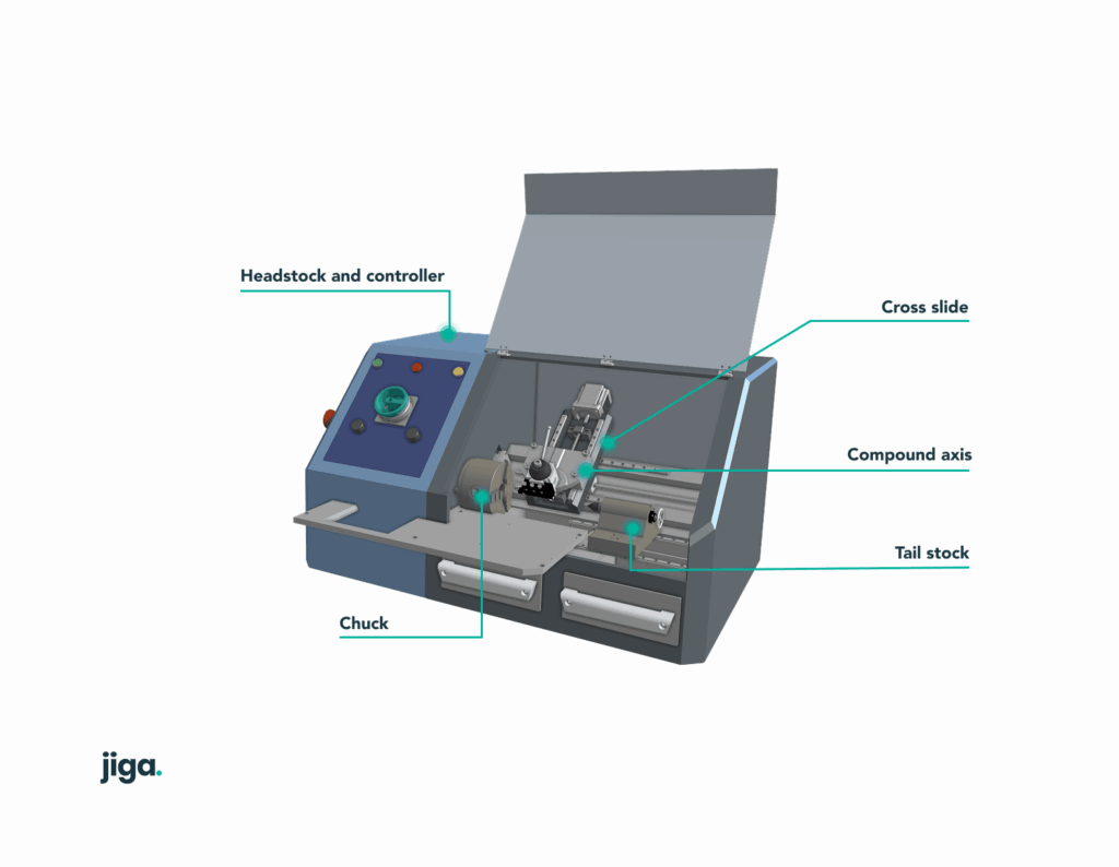
CNC lathes consist of several critical components, each contributing to accuracy, stability, and operational capability. Understanding these components allows engineers to specify parts correctly and select suppliers capable of meeting design requirements.
| Component | Function | Key Notes for Engineers |
|---|---|---|
| Headstock | Houses spindle and main drive | Determines maximum workpiece speed and diameter |
| Spindle & Chuck | Rotates and secures workpiece | Capacity affects max part diameter and clamping style |
| Tailstock | Supports long workpieces | Optional in CNC; provides axial support for slender parts |
| Lathe Bed | Guides linear movement of carriage and turret | Rigid bed ensures accuracy and minimizes vibration |
| Carriage | Moves tools along X/Z axes | Enables turning, facing, and threading operations |
| Tool Turret | Holds multiple cutting tools | Live tooling allows milling and drilling in one setup |
| CNC Control | Executes G-code instructions | Key for precision, repeatability, and complex geometries |
Headstock
The headstock contains the main spindle and drive motors, defining the maximum rotational speed and the workpiece diameter that can be machined. For high-precision applications, engineers must ensure the supplier’s spindle speed aligns with the material’s cutting requirements.
Spindle and chuck
The spindle rotates the workpiece, while the chuck secures it. Engineers must consider jaw style, clamping force, and maximum part diameter when designing components for CNC lathe production.
Tailstock
Tailstocks provide support for long shafts or slender workpieces, and also allows presentation of on-axis drills and threading tools. While optional on many CNC lathes, specifying tailstock support in the design phase can prevent deflection, chatter, and tolerance deviations. However, these decisions should be made in concert with the supplier, to avoid introducing unnecessary process complexities out of an over-abundance of caution from the designer.
Lathe bed
The lathe bed provides the rigid foundation for linear motion of the carriage and turret, carrying slide components that allow smooth on-axis motion of the main carriage. The bed’s rigidity directly impacts vibration dampening and achievable tolerances.
Carriage
The carriage moves along X and Z axes, and mounts tool holders and secondary tool-positioning axes for turning, facing, and threading operations. Its motion speed, precision, and repeatability are critical for achieving consistent part quality. Again, all axes will typically integrate position measurement means, to allow closed loop control of axis positions in real time.
Tool turret
The tool turret holds multiple cutting tools and rotates to present the correct tool for each operation. Engineers designing multi-feature parts must understand which features require live tooling or simultaneous milling operations. Live tooling is an intermediate step between a lathe and a multi-axis machining center. For example, an off-axis positionable drive with a drill chuck allows the spindle to be used as an angle head, locking the workpiece and allowing drilling/threading in precise positions on a PCD (pitch circle diameter), obviating the need for a secondary process setup on other equipment.
CNC control system
The CNC control executes the programmed G-code (positional instructions for tool placement and motions between cuts), coordinating spindle rotation, tool movement, and feed rate. Advanced controls (e.g., FANUC or Siemens) allow complex geometries, precise tolerances, and repeatable production.
Additionally, M-code commands instruct machine specific functions such as coolant provision, tool changes, or robotic loading/unloading.
How a CNC lathe works
The CNC lathe process begins with a CAD model of the part. Engineers or programmers then generate a CAM toolpath, which translates the design into a series of instructions (G-code). During operation:
- The workpiece is secured in the spindle or chuck.
- Required tooling is positioned on the tool turret or tool post. Alternatively, tooling at the tailstock, for drilling, threading and other operations is mounted.
- The spindle rotates the part at a defined speed.
- The carriage and tool turret move linearly along X and Z axes to present the tool at the required position to remove the required material.
- Operations such as turning, facing, threading, boring, or parting are performed according to the toolpath.
- Multiple passes are typically required to extract required surfaces – starting with deeper cuts for roughing and progressing to increasingly fine finishing cuts, depending on tolerance and surface finish demands.
- The finished part is released from the chuck, often requiring minimal secondary operations. Most CNC lathes integrate robotic load/unload, to enable potential lights-out operation and reduced intervention.
| Operation | Description | Typical Applications |
|---|---|---|
| Turning | Removes material along the part’s diameter | Shafts, pins, bushings |
| Facing | Produces a flat end surface | Flanges, end caps |
| Threading | Cuts internal or external threads | Screws, threaded shafts |
| Boring | Enlarges or re-machines holes | Precision fit holes |
| Parting | Cuts off finished parts | Component separation |
For engineers and designers specifying the need for turned parts, understanding this workflow clarifies design decisions, such as specifying diameters, grooves, or threads that align with machine capabilities.
Types of CNC lathes
Choosing the right lathe type is essential for achieving precision, efficiency, and part quality.
| Lathe Type | Workpiece Orientation | Best For | Pros | Limitations |
|---|---|---|---|---|
| Horizontal | Spindle horizontal | Standard shafts & rods | Versatile, common | Floor space required |
| Vertical | Spindle vertical | Large/Heavy parts | Easier loading/unloading | Limited tooling options |
| Swiss-Type | Horizontal with guide bushing | Long, slender parts | Tight tolerances, high precision | Small diameters only |
| Live Tooling / Mill-Turn | Horizontal or Swiss | Complex multi-feature parts | Combine turning + milling in one setup | Higher setup & programming cost |
Horizontal CNC lathes
This is overwhelmingly the most common format, suitable for medium to large parts, autofeed of long bar-stock and high productivity. They are ideal for general turning operations and high-volume production, but offer limited weight and diameter extremes that can be an issue in larger components.
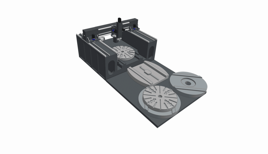
Vertical CNC lathes
The spindle is orientated vertically, making it easier to handle heavy or large-diameter components. Used in aerospace (larger turbine parts), shipbuilding (medium speed and low speed oil engine parts, drive train components, capstains, steering gear etc.), and industrial machinery.
Swiss-type CNC lathes
Designed for long, slender, or high L:D (length:diameter) ratio parts. The guide bushing supports the workpiece near the cutting point, allowing for tighter tolerances on thin features. Typically the main axis motion moves the part and not the tool, enabling very stable and smooth operation, despite dangerous part-flexibility.
Live tooling and mill-turn lathes
These combine turning and milling in one setup, reducing handling and setup time. This is essential for parts with drilled holes, milled flats, or complex multi-feature designs, to avoid the need for secondary setups and the associated loss of precision.
Applications of CNC lathe machining
CNC lathes are universally and extensively used in industries where precision, repeatability, and complex cylindrical features are required:
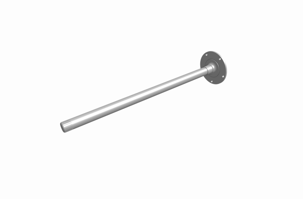
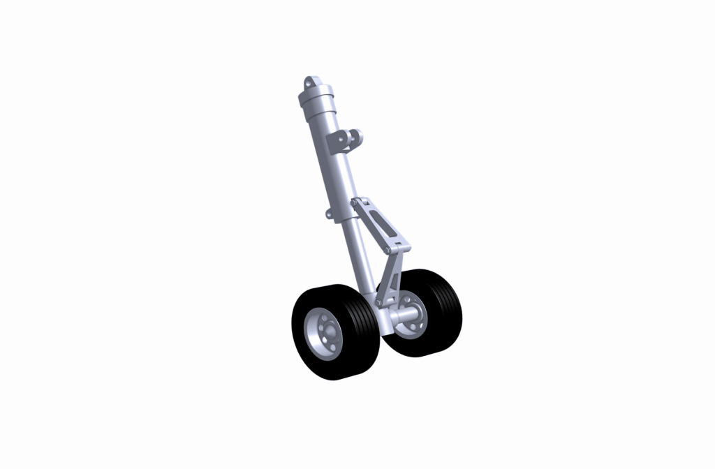
- Aerospace: Actuator shafts, bushings, hydraulic fittings.
- Automotive: Axles, engine components, EV motor components, drive train elements, suspension parts.
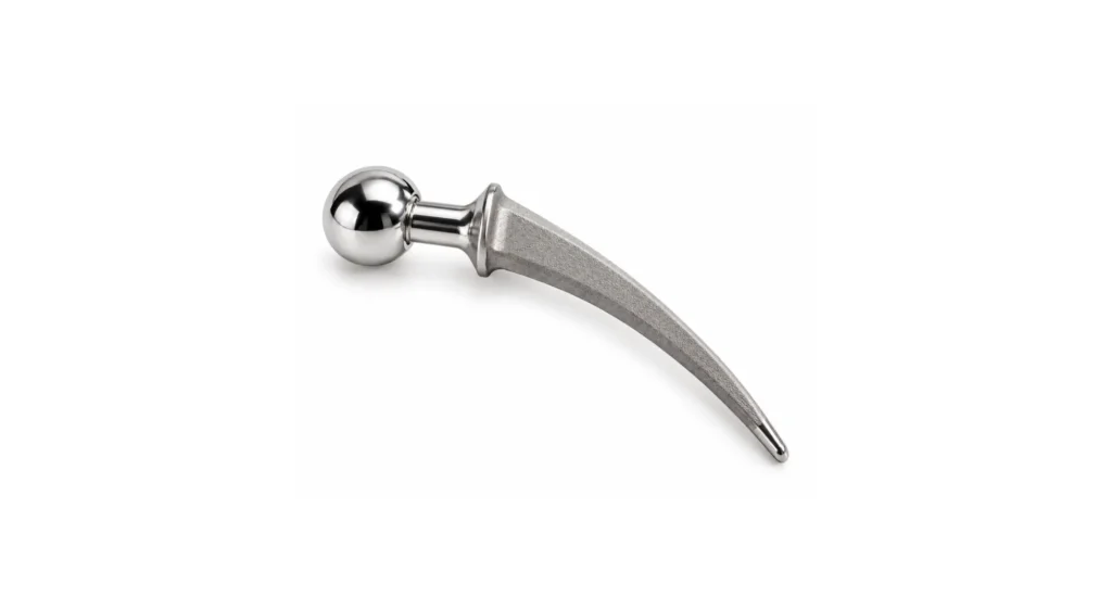
- Medical Devices: Surgical screws, bone plates, implants.
The turning process is essential wherever tight tolerances, surface finish, and repeatable performance of cylindrical features/parts directly impact safety, functionality, and reliability.
Benefits of CNC lathe machining
- Precision and repeatability: CNC operation ensures dimensional accuracy and repeatability across multiple parts and batches.
- Reduced human error: Automated operation eliminates manual inconsistencies, altering the skill-chain and increasing productivity/reducing waste.
- Production efficiency: Continuous operation and multi-tool turrets reduce cycle times. Bar feeders and robot load/unload render processing hands-off and lights-out.
- Complex geometry capability: Multi-axis control allows threading, grooving, and cross-hole machining in a single setup.
- Live tools: These allow limited milling operations to be performed, eliminating equipment changes and repeat setup inaccuracies.
CNC lathe tolerances and surface finish
Typical tolerances achievable on CNC lathes:
- General turning: ±0.01 mm
- Precision shafts: ±0.002–0.005 mm
- Threaded features: ±0.01 mm
Surface finish depends on tool selection, feed rates, material properties, and cutting speed. Engineers should specify target tolerances and finishes early in design to ensure the supplier can meet requirements. Over specifying surface finish requirements can considerably slow operations, requiring fine finishing cuts that demand lower feed rates and even new tooling.
CNC lathe vs. CNC mill
CNC lathes primarily rotate the workpiece, while CNC mills rotate the cutting tool – multi axis CNC machines blur the differentials between the two classes. Lathes are best for cylindrical, rotationally symmetric parts, whereas mills are ideal for prismatic or complex surfaces. Mill-turn centers combine both capabilities for complex shafts, PCD hole preparation, or multi-feature components.
Finding a CNC turning supplier
Key factors for sourcing:
- Programming expertise: Experienced operators ensure optimal toolpaths. Such skills integrate the instincts of a skilled machinist with deep programming skills, making this a valuable category of staff.
- Direct communication: Discuss tolerances, materials, and finishes directly with the operator executing the work, for reliable information.
- Machine and tooling capabilities: Confirm spindle speed, chuck size, tooling types/sizes, and axis range.
- Consistency: Same setup and programmer across production runs ensures repeatable quality and fewer ramp-up disruption risks.
Summary
CNC lathe machining transforms digital (CAD) designs into precise, turned components using computer-controlled rotation and cutting, derived from CAM interpretations of the data. Understanding machine components, types, operations, and tolerances helps engineers design parts that are achievable, cost-effective, and high quality while facilitating clear communication with suppliers.